Skip to content
  • English
    • French
    • Italian
    • Spanish
    • German
    • Dutch
    • Portuguese (Portugal)
    • Greek
    • Polish
  • English
    • French
    • Italian
    • Spanish
    • German
    • Dutch
    • Portuguese (Portugal)
    • Greek
    • Polish
Logo Avidsen
  • Products
    • Products
    • Avidsen Brand
    • Extel Brand
    • Philips Brand
    • Thomson Brand
  • Support
    • Tutorials on repair and use
    • Avidsen Technical Support
    • Extel brand technical support
    • Philips technical support
    • Thomson Technical Support
  • The Group
    • The Group
    • Contact
  • Ethic Company
  • Where to buy ?
\

AVLO pre-diagnosis

  1. Home
  2. AVLO pre-diagnosis

AVLO pre-diagnosis

In this tutorial, we'll look at the faults that can be encountered by the 24V swing gate circuit board, how to clearly identify them, and what to do about them.

This tutorial is applicable for:

Avidsen - 114170 - Stryrka 310 / Avidsen - 114173 - Teha 410 / Avidsen - 114174 - Teha Connect / Avidsen - 114200 - Orane 410 / Avidsen - 114201 - Orane 510 / Avidsen - 114202 - Orane Connect / Avidsen - 114300 - Teha 320 / Avidsen - 114301 - Stryrka 320T / Avidsen - 114302 - Orane 420 / Thomson - 510062 - Sésame 250
Difficulté : Moderate
Temps nécessaire : 1 minutes
Nombre d’étapes : 4
Mise à jour : February 2025

Tutorial steps:

No electrical start-up of the board

The board does not start up electrically, nor does it light up its green and red LEDs when powered up or when waking from standby by pressing one of its buttons.

  • Check transformer input (230V AC) and output voltage (20-22V AC)
    • Replace 5A fuse if necessary
  • In the case of a battery power supply and solar panel, make sure that the motorization output of solar kit is connected to the BAT terminals on the electronic board.
  • Make sure 24VDC voltage is present on BAT terminals.

Radio communication problem

The electronic board does not respond when a remote control button is pressed or a code is entered on the wireless keypad.

First of all, check that the remote control is working properly (indicator lights up when a button is pressed, battery replaced, etc.).

We recommend you carry out the tests using several remote controls, in order to avoid a technical problem on a single remote control.

  • Check that no error code is displayed by the electronic board (self-learning, obstacle, etc.).
    • If a code appears, please refer to the table on instructions or to this tutorial to correct the error.
  • Check that the green LED L0 on the circuit board flashes when the remote control is pressed.
    • If the green LED L0 does not flash, the electronic board is out of service.
  • Check that the green LED is not flashing continuously.
    • Card interference. Identify and eliminate the radio interference source.
  • Reset the radio memory and start programming again.

If radio range is lost :

  • Check remote control range
    • If the range is less than 2m, the electronic board is potentially out of order.
    • If the range exceeds 2m, the card may be jammed.

If the card reacts when it is off standby (LED L0 on) but does not react when it is on standby (LED L0 off) :

  • Check if a product is connected as a dry contact on the board.
    • Unplug the product in question and perform an electrical reboot of the board.
    • Check the supply voltage (press OK on the board).
      • If the red lights are off, disconnect the accessories from the board (light and photocells).
      • If the red LEDs still do not light up, the circuit board is out of service.

Untimely start/stop

Your actuator starts without a given command, or stops on its own during a cycle without an error code.

  • Check if a product is connected as a dry contact on the board.
    • Unplug the product in question and perform an electrical reboot of the board.
  • Reset the radio memory and start programming again.

No detection by photocells

The map does not take into account your passage in front of the photocells:

  • Check that the shunt between GND and PHO has been removed from the board.
  • Restart a self-learning operation, and check that the gate closes properly.
    • Correct the polarity of connection motors if necessary (see here).

The card takes into account your passage in front of the photocells, but only at the beginning and end of the closing cycle:

  • Connect a wire between the motor’s metal frame and a GND input on the board.


Single-leaf operation

The card controls only one motor (M1) in opening and closing, without indicating any error on the LEDs.

  • Reset the card to 2-leaf mode
    • Menu 2 Item 3 on the map (see image opposite)

Error with code displayed by the card: Foreword

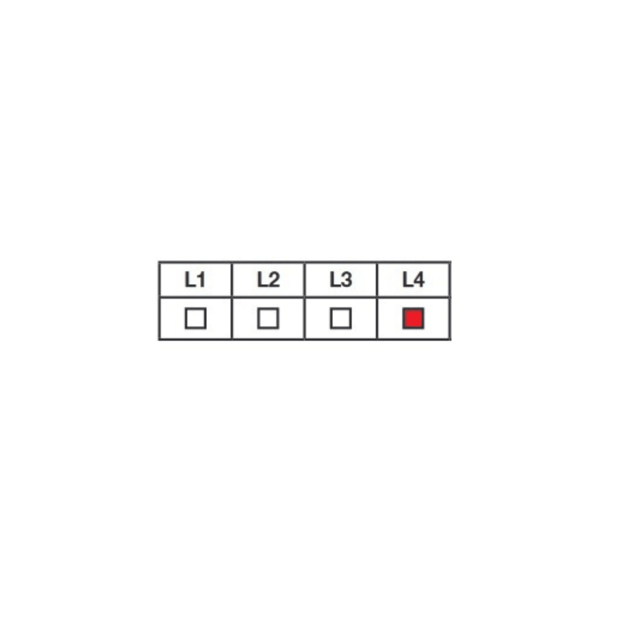
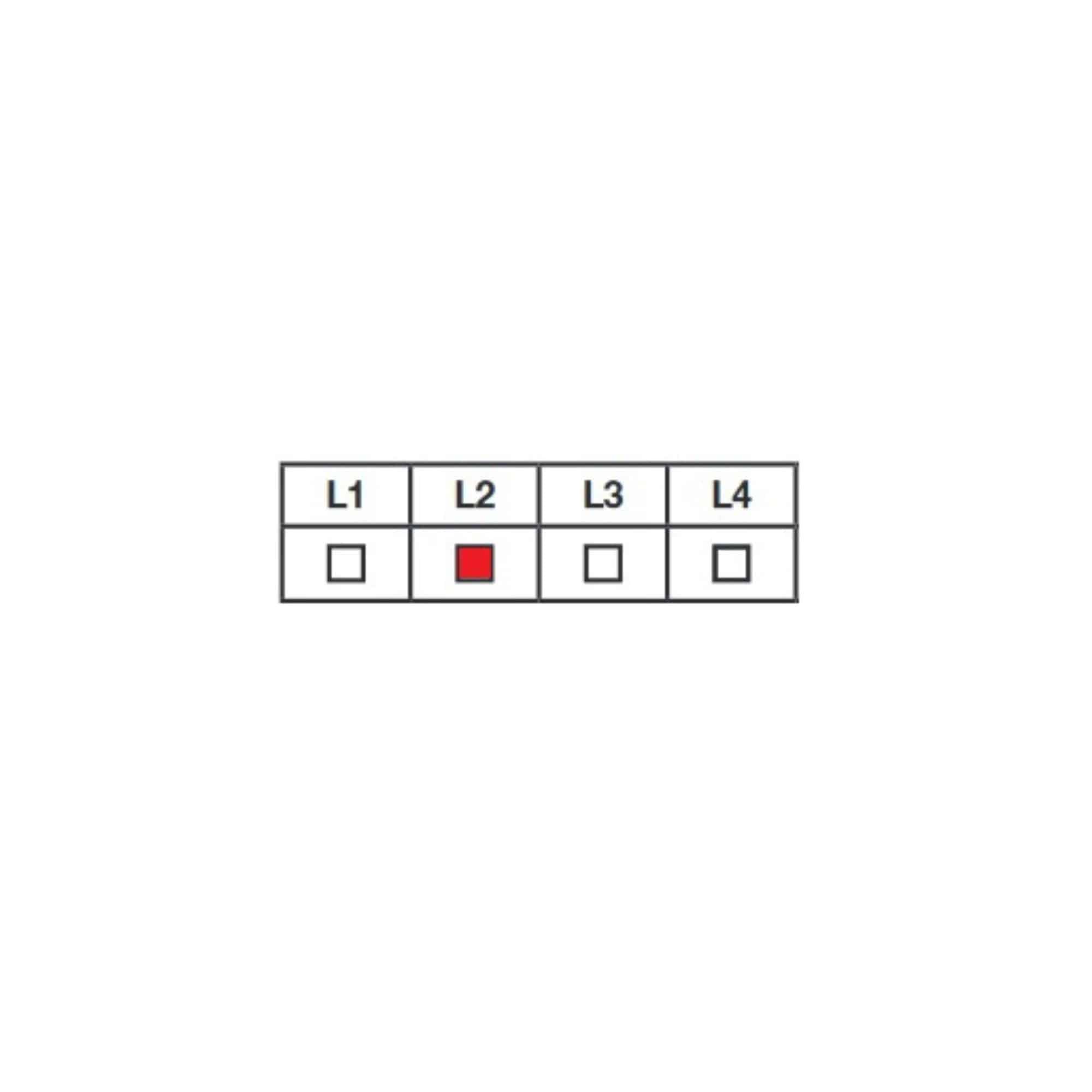
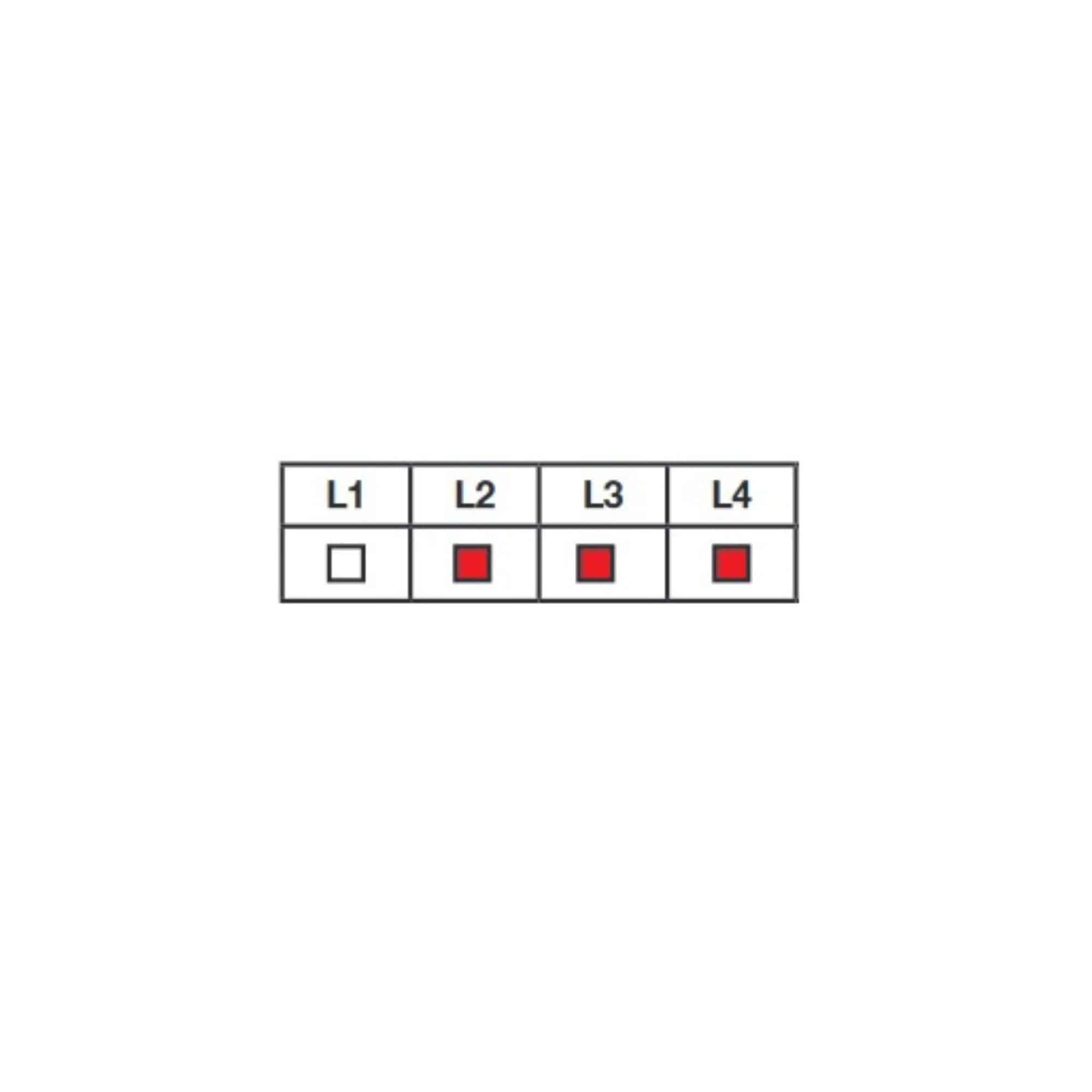
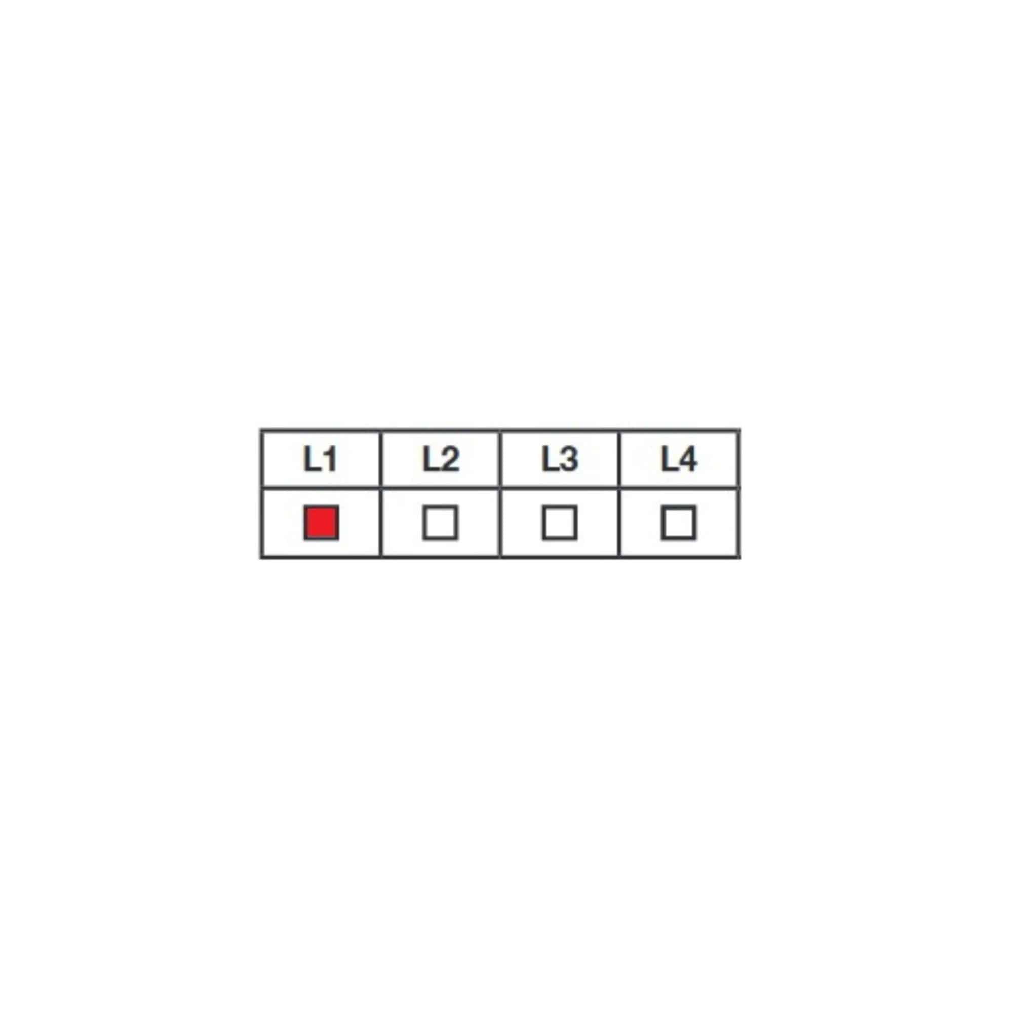
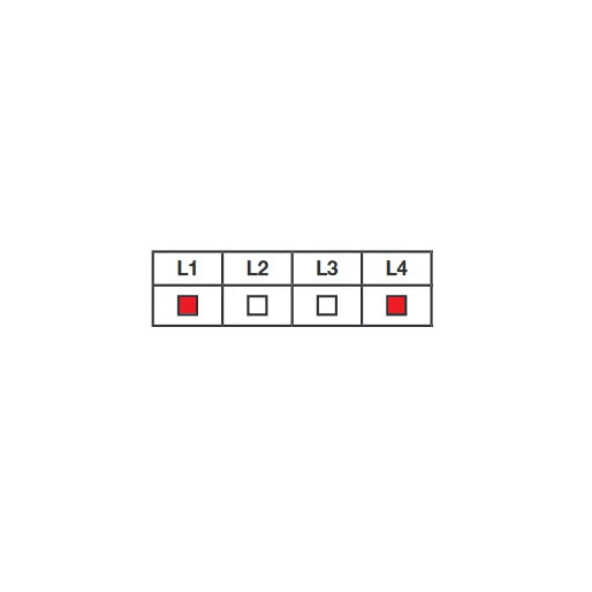
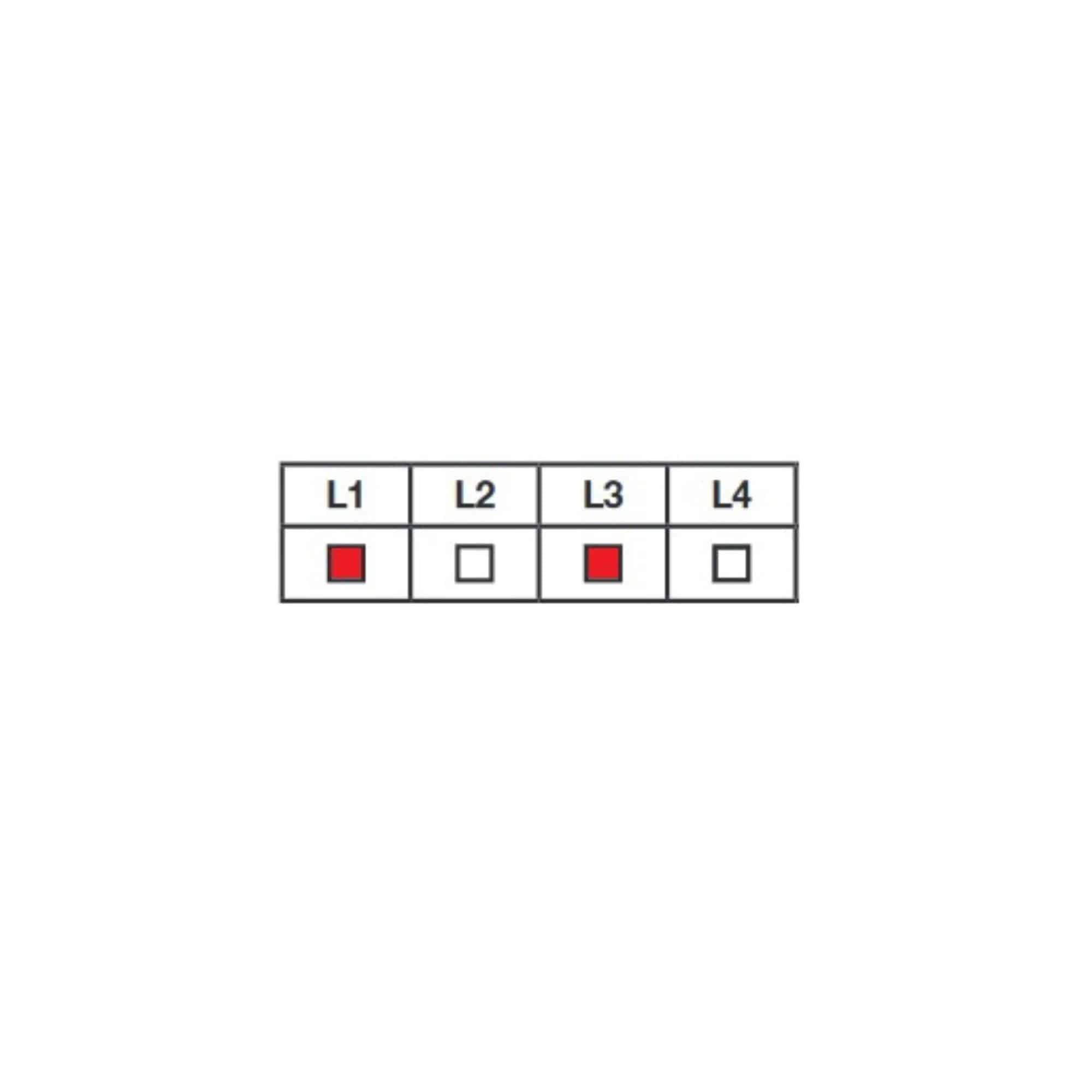
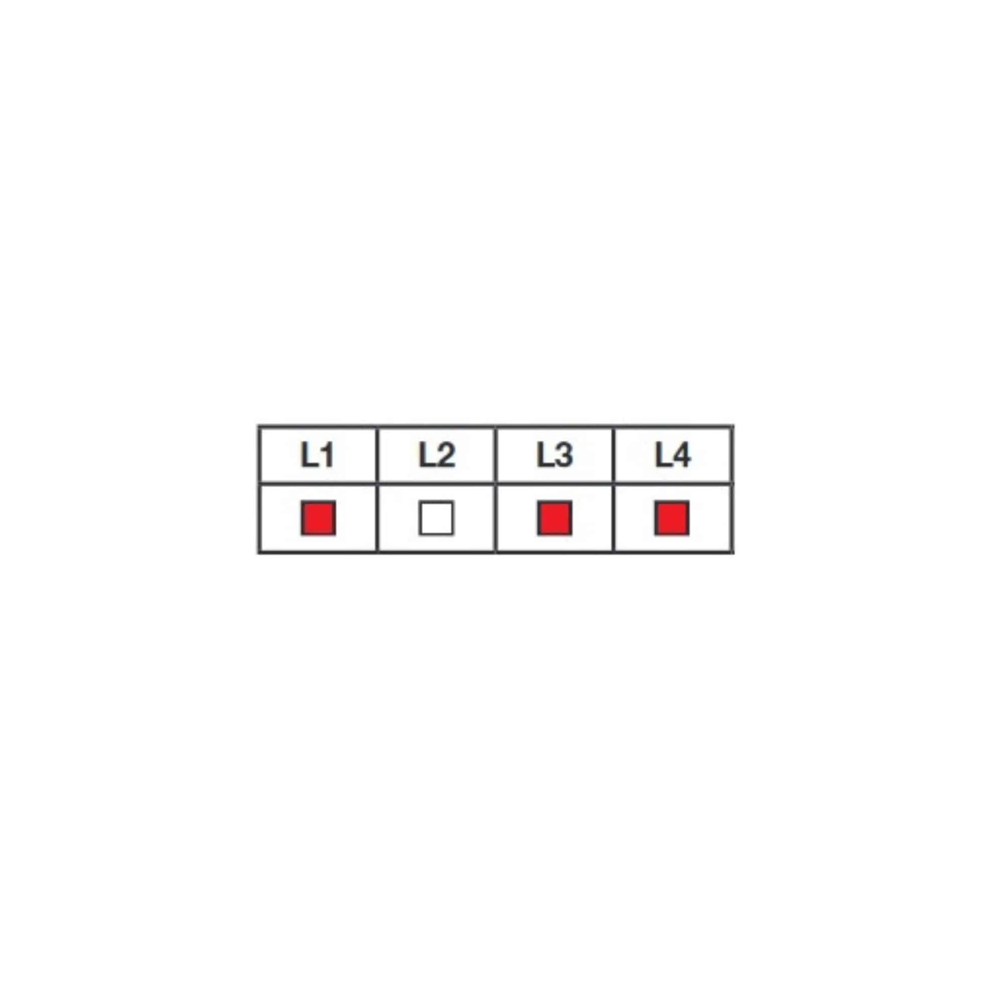
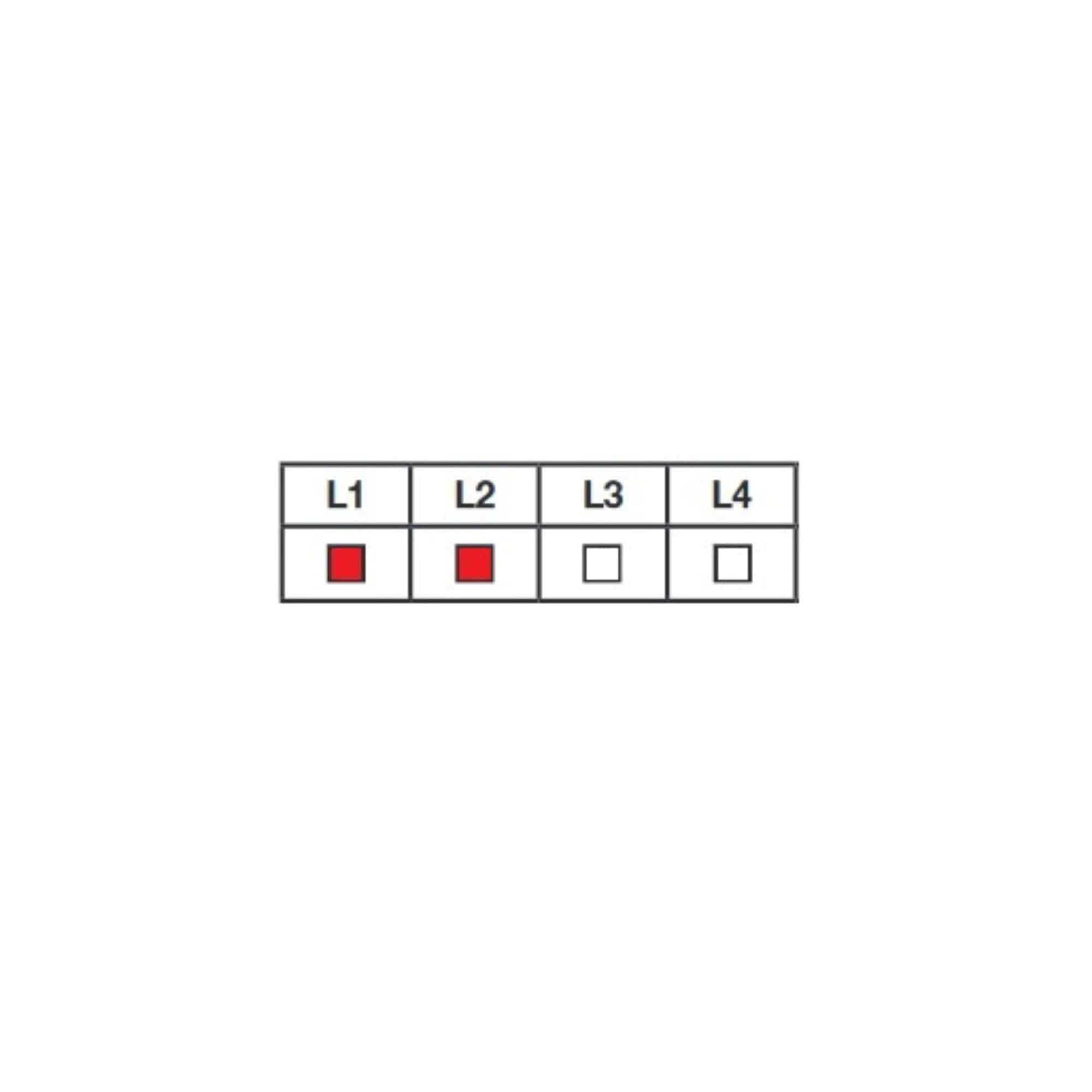
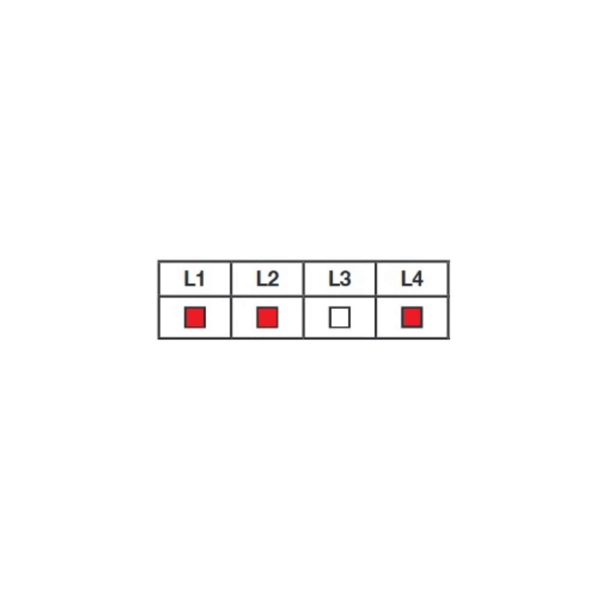
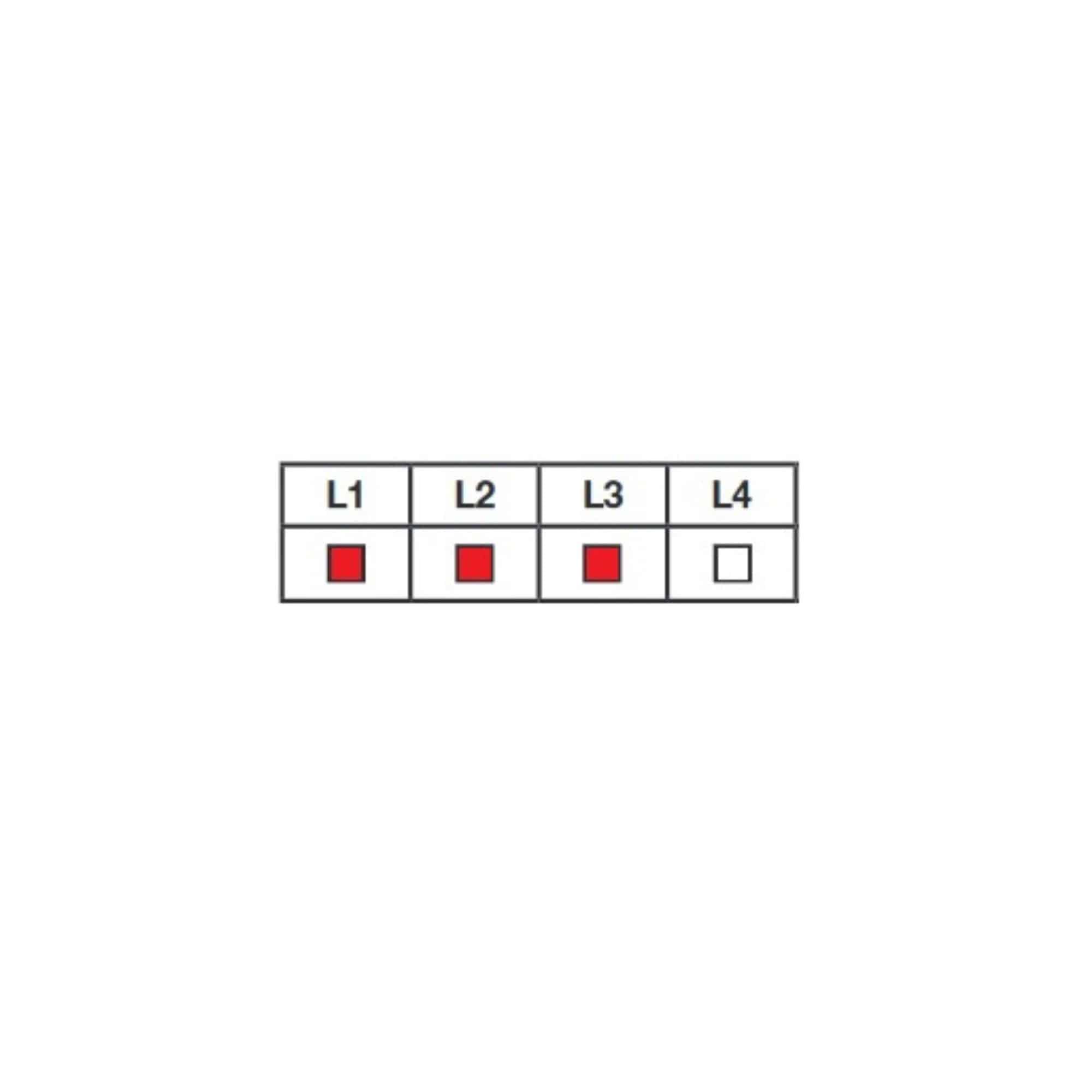
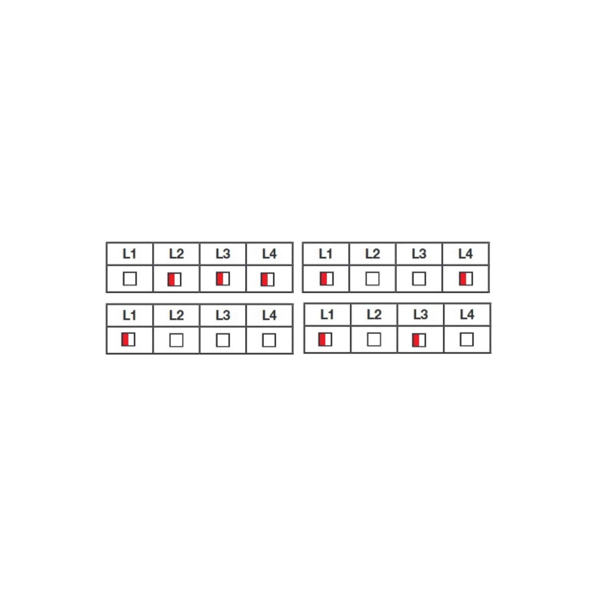
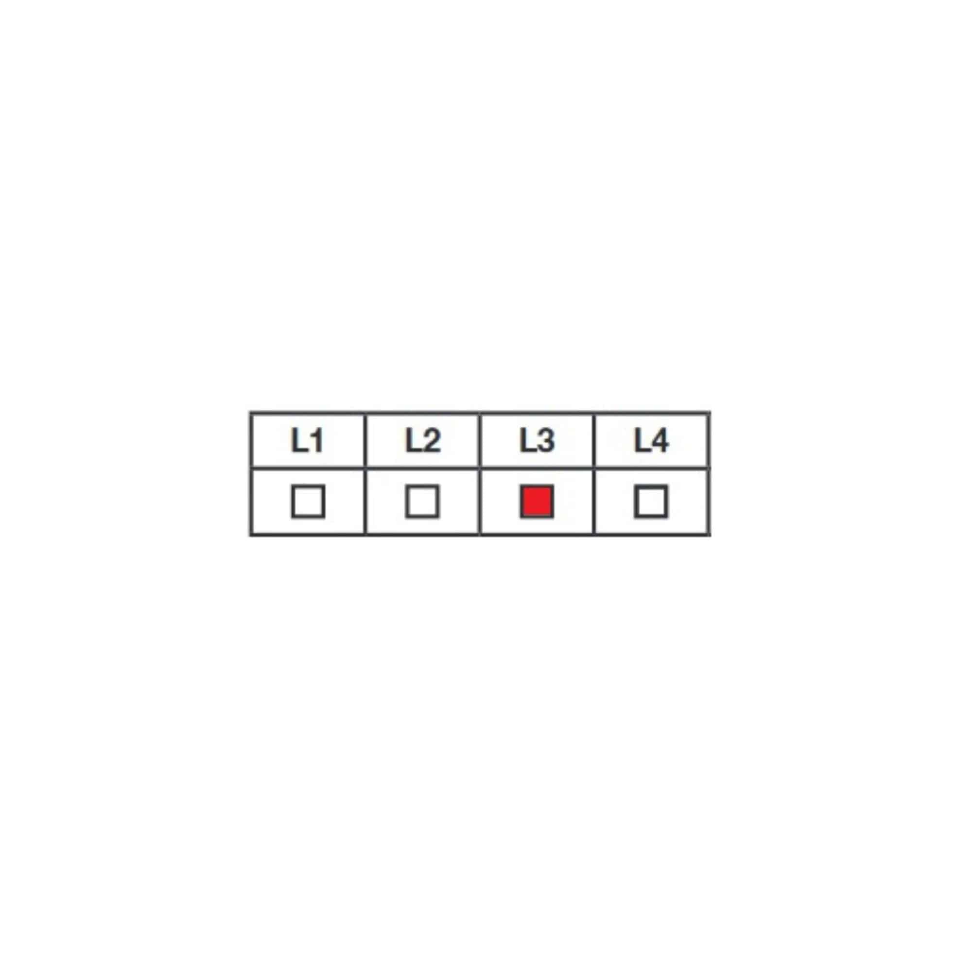
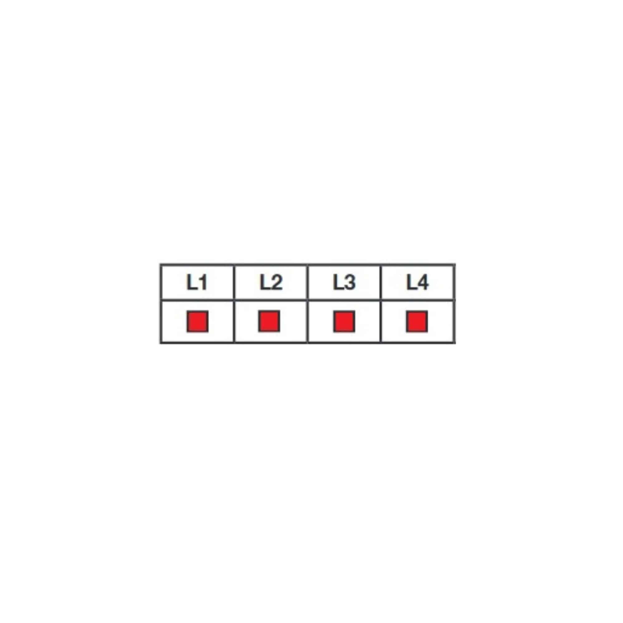
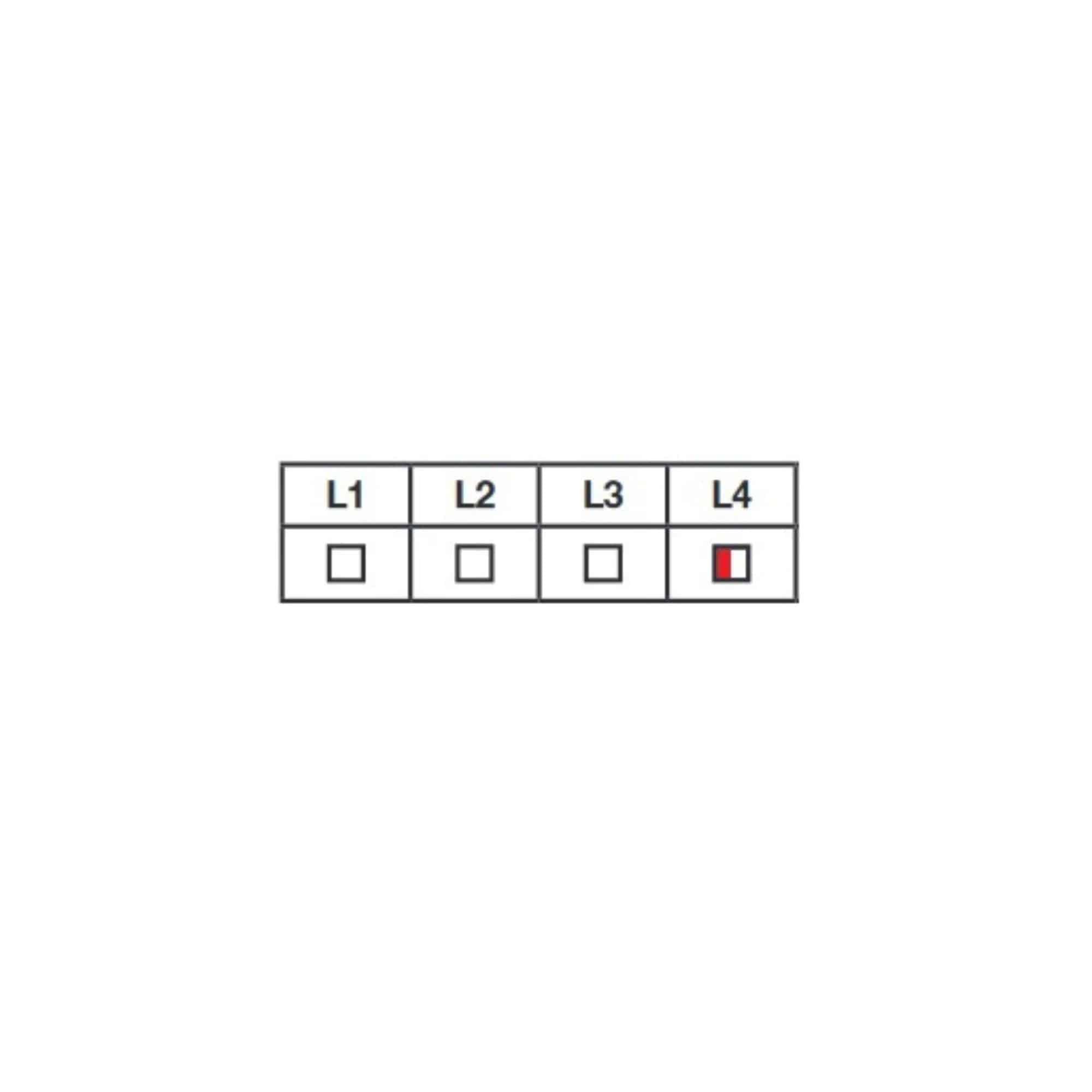
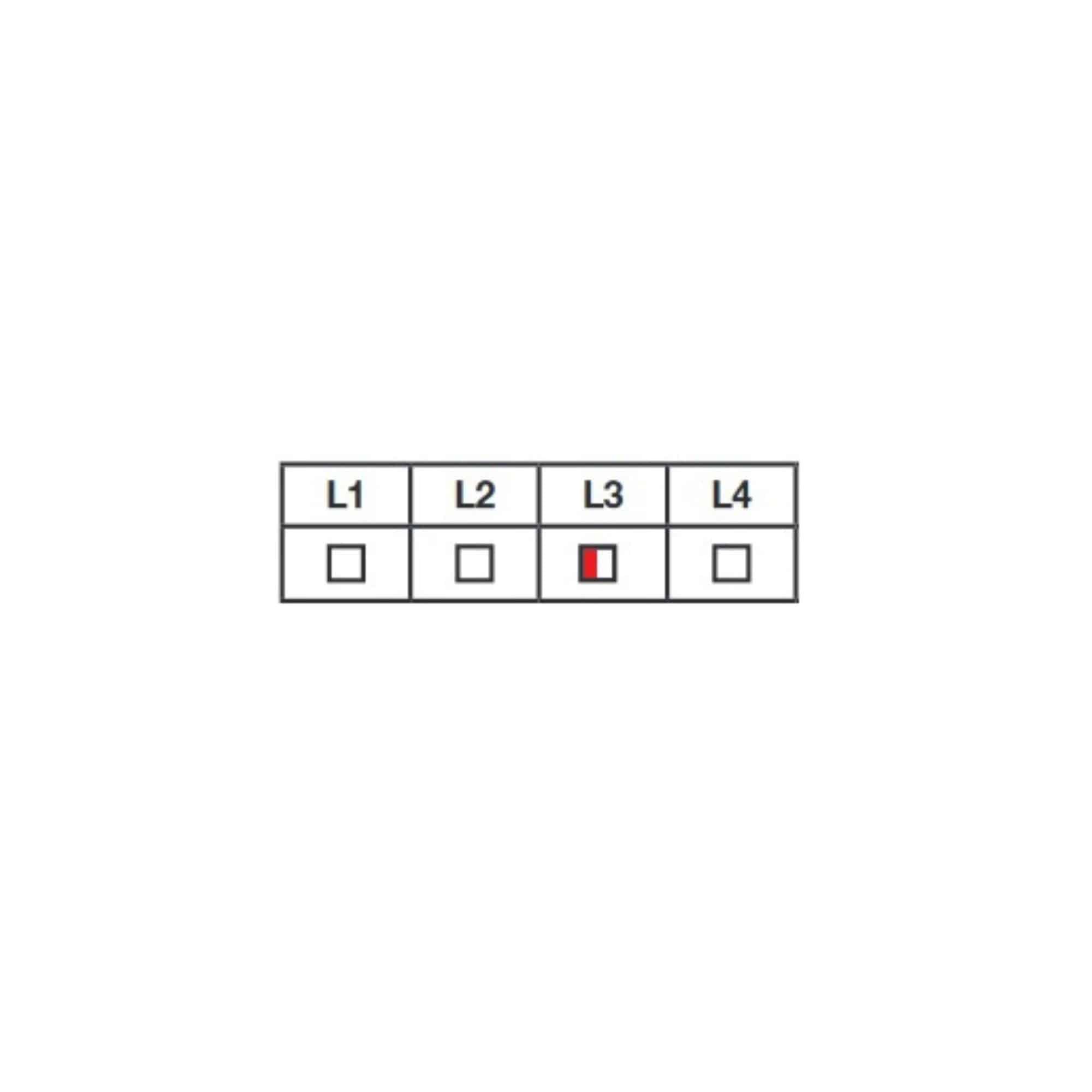
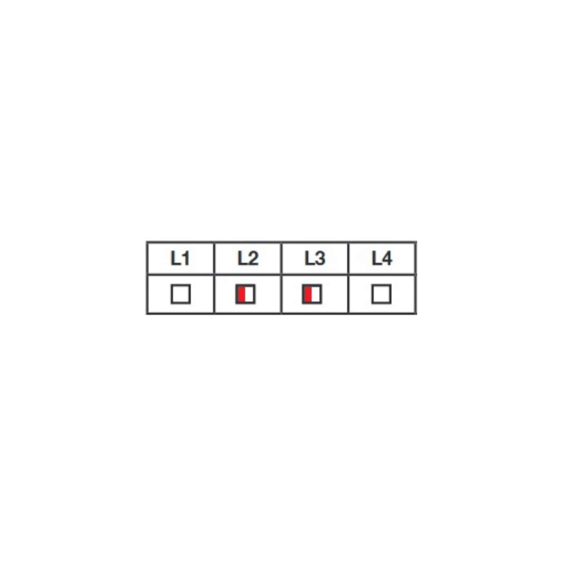
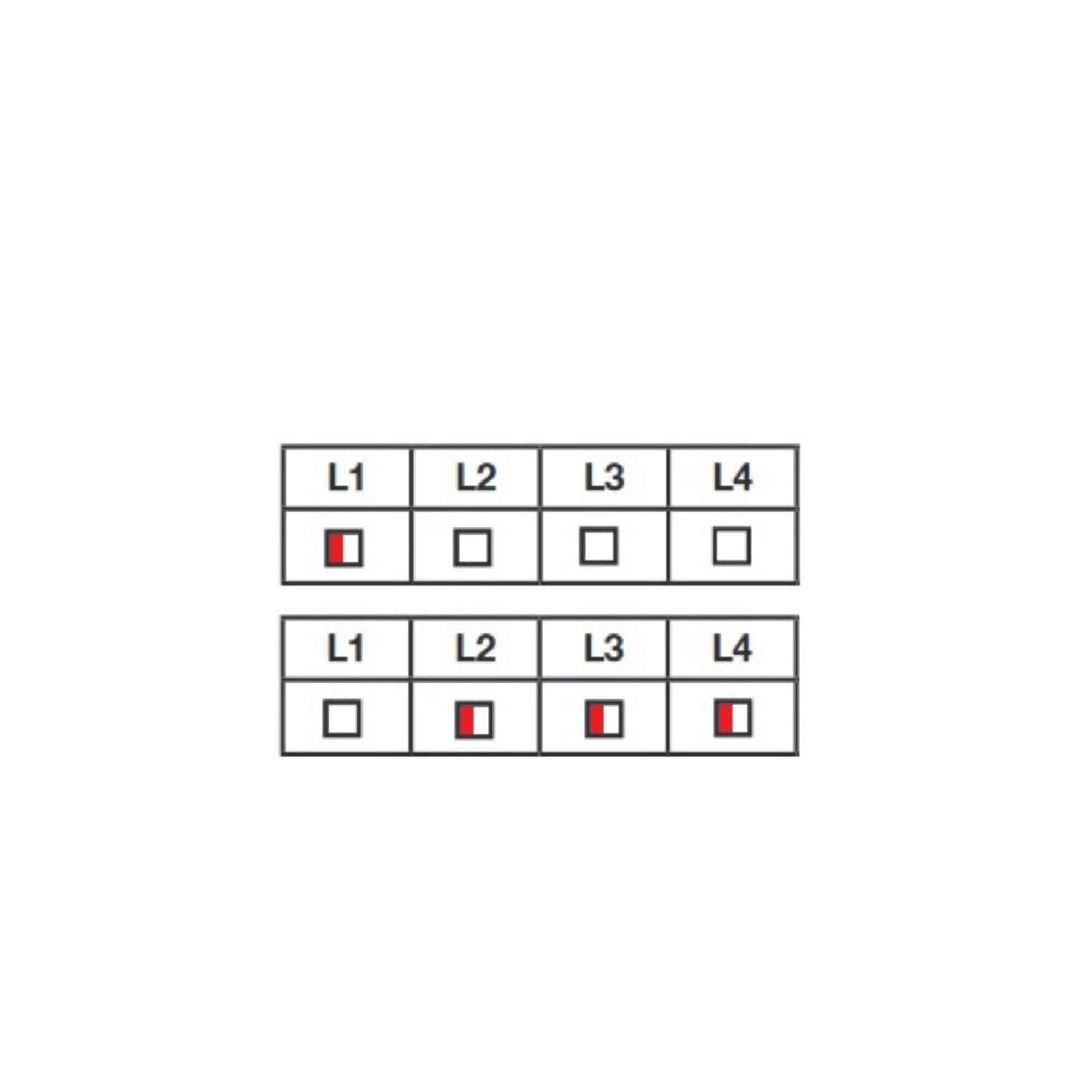
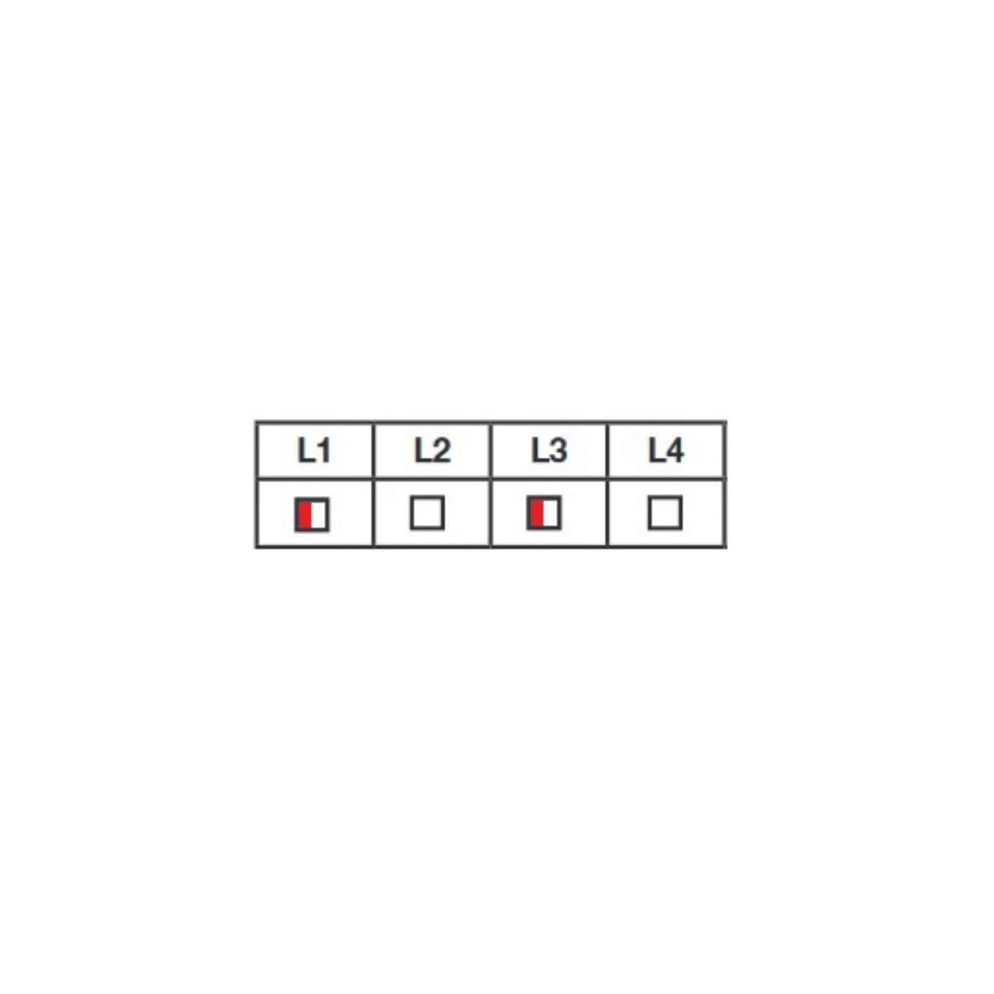
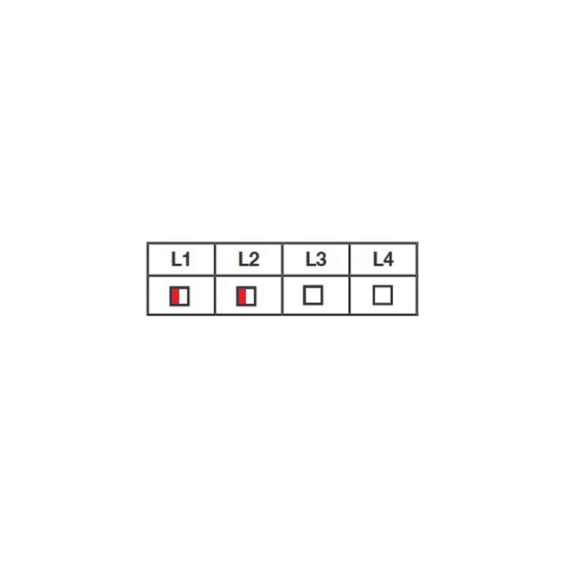
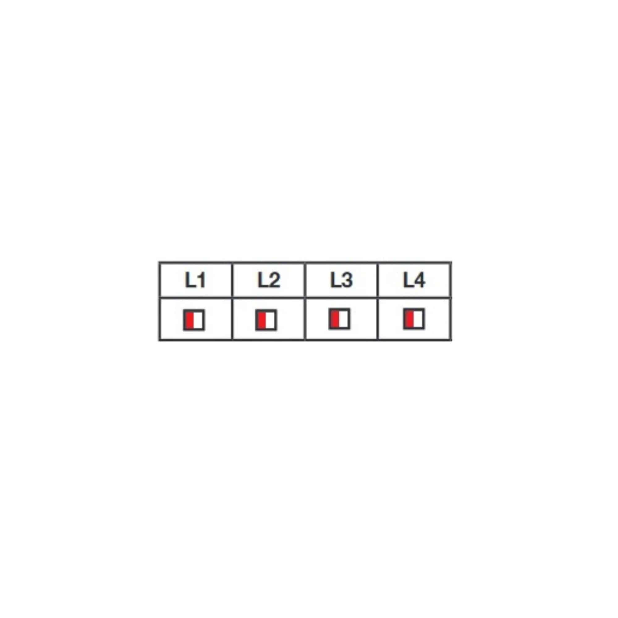
When the card encounters an error, either during a self-learning phase or during an operating cycle, it will stop the current cycle and display one or more red LEDs.

It’s important to note this error code in order to understand what’s going on.

ATTENTION:

Self-learning and operating cycle (command given by remote control or dry contact) have similar error codes (same LED lighting up), but different meanings.

So pay attention to the operation the card is performing when the error occurs, to know which code to refer to.

Self-learning L4 Fixed: In phase 0, leaf M1 has not found a stop after 60s of closing.

This error code indicates that the board did not see the current peak of the M1 electric motor when the gate reached the limit stop during the first closing phase self-learning.

  • Check the board voltage and power supply.
    • If powered by solar kit, check the voltage of each battery disconnected from solar kit.
  • Check the strength in the card settings .
    • Reduce force if necessary.
  • Check the installation of the motor on the leaves.
    • If the installation dimensions are not respected, the peak current may not be sufficient to be detected by the card.
  • Perform a cross-test (see Appendix 1)
    • If the fault follows the electric motor (the error code changes): Motor out of order
    • If the error code is identical: Card out of order


Teach-in L2 Fixed: In phase 0, leaf M2 has not found a stop after 60s of closing.

This error code indicates that the board did not see the current peak of the M2 electric motor when the gate reached the stop during the first closing phase self-learning.

  • Check the board voltage and power supply.
    • If powered by solar kit, check the voltage of each battery disconnected from solar kit.
  • Check the strength in the card settings .
    • Reduce force if necessary.
  • Check the installation of the motor on the leaves.
    • If the installation dimensions are not respected, the peak current may not be sufficient to be detected by the card.
  • Perform a cross-test (see Appendix 1)
    • If the fault follows the electric motor (the error code changes): Motor out of order
    • If the error code is identical: Card out of order


Teach-in L2,3 and 4 Fixed : In phase 0, motor M1 has not been detected

This error code indicates that the board has not seen any current drawn by the electric motor connected to M1.

  • Check the connection motor on the map.
  • Perform a cross-test (see Appendix 1)
    • If the fault follows the electric motor (error code changes) : HS
    • If the error code is identical: Card out of order


Teach-in L1 Fixed: In phase 0, motor M2 has not been detected

This error code indicates that the board has not seen any current drawn by the electric motor connected to M2.

  • Check the connection motor on the map.
  • Perform a cross-test (see Appendix 1)
    • If the fault follows the electric motor (the error code changes): Motor out of order
    • If the error code is identical: Card out of order


Self-learning L1 and 4 Fixed : In phase 1, the M1 motor has found the stop within 3s of opening.

This error code indicates that the card thinks that the M1 leaf has reached its opening stop in less than 3s, whereas the gate has started from its closed position.

  • Self-learning began with the open M2 and closed M1.
    • Disengage the motors or use manual control to bring the leaves to half-open position
  • Check the connection motor on the map.
    • Check that the motor for the overlapping leaf is M1.
  • Check the strength in the card settings.
    • Increase force if necessary
  • Check that the motor is correctly installed on the leaf.
    • If the dimensions are not respected, the actuator may open too quickly or consume too much electrical current.


Self-learning L1 and 3 Fixed : In phase 1, the M2 motor has found the stop within 3s of opening.

This error code indicates that the card thinks that gate leaf M2 has reached its opening stop in less than 3s, whereas the gate has started from its closed position.

  • Check the connection motor on the map.
    • Check the polarity of the motors on the board at connection.
  • Check the strength in the card settings.
    • Increase force if necessary
  • Check the installation of the motor on the leaf.
    • If these dimensions are not respected, the actuator may open too quickly or consume too much electrical current.


Self-learning L1,3 and 4 Fixed : In phase 1, leaf M1 has not reached the stop after 60s of opening.

This error code indicates that the electronic board did not see the current peak of the M1 motor when it reached its opening stop.

  • Check the board voltage and power supply.
    • If powered by solar kit, check the voltage of each battery disconnected from solar kit.
  • Check the strength in the card settings.
    • Reduce force if necessary.
  • Check the installation of the motor on the leaves.
    • If the installation dimensions are not respected, the peak current may not be sufficient to be detected by the card.

Self-learning L1and 2 Fixed : In phase 1, leaf M2 has not reached the stop after 60s of opening.

This error code indicates that the electronic board did not see the current peak of the M2 motor when it reached its opening stop.

  • Check the board voltage and power supply.
    • If powered by solar kit, check the voltage of each battery disconnected from solar kit.
  • Check the strength in the card settings.
    • Reduce force if necessary.
  • Check the installation of the motor on the leaves.
    • If the installation dimensions are not respected, the peak current may not be sufficient to be detected by the card.

Teach-in L1,2 and 4 Fixed : In phase 1, motor M1 has not been detected

This error code indicates that the electronic board has not seen any current consumption by the M1 motor during the opening phase.

  • Check the connection motor on the map.
    • Disconnect and reconnect the motor to the board.
  • Restart self-learning.
    • If the error code persists, the card is out of service.


Teach-in L1,2 and 3 Fixed : In phase 1, motor M2 has not been detected

This error code indicates that the electronic board did not see any current consumption by the M2 motor during the opening phase.

  • Check the connection motor on the map.
    • Disconnect and reconnect the motor to the board.
  • Restart self-learning.
    • If the error code persists, the card is out of service.


Self-learning Flashing LEDs : Motor not recognized

These error codes indicate that the board has failed to calculate motor currents correctly.

  • Change the speed setting in the map settings.
    • Reduce speed.
  • Restart self-learning.
    • An external element may have disrupted the calculation.
  • Check the installation of the motor on the leaves.
    • If the installation dimensions are not respected, the peak current may not be sufficient to be detected by the card.

Operation L4 Steady: An obstacle has been detected on M1 during closing.

This error code indicates that the board has detected overconsumption of the M1 motor for a given time during a closing cycle.

This error code is normal if the leaf has been held back by an obstacle, or possibly a prolonged gust of wind.

If the fault persists :

  • Restart self-learning.
    • Check that the self-learning process is running smoothly and that the fault has disappeared.
  • Modify the force setting on the card.
    • Increase the force setting.
  • Check motor installation on gate
    • In the event of non-compliant dimensions, the motorization may consume too much electrical current.

If this error code appears when the motor reaches the closing stop:

  • Change the stop tolerance setting.
    • Increase the value to maximum.

Operation L3 Fixed: An obstacle has been detected on M2 during closing.

This error code indicates that the board has detected overconsumption of the M2 motor for a given time during a closing cycle.

This error code is normal if the leaf has been held back by an obstacle, or possibly a prolonged gust of wind.

If the fault persists :

  • Restart self-learning.
    • Check that the self-learning process is running smoothly and that the fault has disappeared.
  • Modify the force setting on the card.
    • Increase the force setting.
  • Check motor installation on gate
    • In the event of non-compliant dimensions, the motorization may consume too much electrical current.

If this error code appears when the motor reaches the closing stop:

  • Change the stop tolerance setting.
    • Increase the value to maximum.

Operation L2,3 and 4 Fixed : Detection by photocells

This error code indicates that the photocells wiring harness was cut during a closing cycle.

This error code is normal if there is an obstacle between the leaves at the start of the closing cycle, or if someone has crossed the beam during a closing cycle.

If you do not have a photocells:

  • Check for good contact and presence of shunt between GND and PHO on the board.
    • Replace shunt, or disconnect it and reconnect it to the board.
    • .

If you have photocells, with no obstacles between photocells:

  • Check connection for photocells
    • Check the presence and good contact of shunt between – and COM on the receiver photocell.
  • Check alignment and power supply photocells.
    • Press PROG on the card once to wake it from standby.
      • Check that the orange LED on the receiver photocell is lit.
        • If the light is off, check the connections on the receiver photocell.
        • If the LED is Red, check the alignment and connection of the transmitter photocell.

L1, 2 and 3 operation Fixed : An obstacle has been detected on M1 at opening.

This error code indicates that the board has detected overconsumption of the M1 motor for a given time during an opening cycle.

This error code is normal if the leaf has been held back by an obstacle, or possibly a prolonged gust of wind.

If the fault persists :

  • Restart self-learning.
    • Check that the self-learning process is running smoothly and that the fault has disappeared.
  • Modify the force setting on the card.
    • Increase the force setting.
  • Check motor installation on gate
    • In the event of non-compliant dimensions, the motorization may consume too much electrical current.

If this error code appears when the motor reaches the closing stop :

  • Change the stop tolerance setting.
    • Increase the value to maximum.

L1,2,3 and 4 operation Fixed : An obstacle has been detected on M2 at opening.

This error code indicates that the board has detected overconsumption of the M2 motor for a given time during an opening cycle.

This error code is normal if the leaf has been held back by an obstacle, or possibly a prolonged gust of wind.

If the fault persists :

  • Restart self-learning.
    • Check that the self-learning process is running smoothly and that the fault has disappeared.
  • Modify the force setting on the card.
    • Increase the force setting.
  • Check motor installation on gate
    • In the event of non-compliant dimensions, the motorization may consume too much electrical current.

If this error code appears when the motor reaches the closing stop:

  • Change the stop tolerance setting.
    • Increase the value to maximum.

Operation L4 Flashing : M1 motor not connected or incorrectly connected

This error code indicates that the board has not seen any current drawn by the electric motor connected to M1.

  • Check the connection motor on the map.
  • Perform a cross-test (see Appendix 1)
    • If the fault follows the electric motor (error code changes: L3 flashing) : Motor out of order
    • If the error code is identical: Card out of order


Operation L3 Flashing : M2 motor not connected or incorrectly connected

This error code indicates that the board has seen no electrical current drawn by the electric motor connected to M2.

  • Check the connection motor on the map.
  • Perform a cross-test (see Appendix 1)
    • If the fault follows the electric motor (error code changes: L4 flashing) : Motor out of order
    • If the error code is identical: Card out of order


Operation L2 and 3 Flashing lights : Leaf M1 closed before leaf M2

This error code indicates that the card has detected the end of the closing travel of leaf M1 before the arrival of leaf M2.

  • Check that the motor is correctly installed on the leaf.
    • If these dimensions are not respected, the actuator may open and close too quickly.
  • Check the difference in opening angle between the leaves.
    • If the angle difference is too great, the mispositioning delay will not be sufficient to prevent M1 from closing before M2. Limit M2’s opening angle.
  • Increase mispositioning closing time
    • See Menu 3 Item 1
    • The maximum mispositioning delay is 4.5 s.
  • Check that motor 1 still has its end-of-stroke acceleration and idling.
    • If not : Card out of order


L1 flashing and L2, 3 and 4 flashing operation: Consecutive obstacle detection

These error codes indicate that the card has consecutively detected several obstacles (over-consumption of a motor for a given time during an opening or closing cycle).

This error code is normal if the leaf has been held back by an obstacle, or possibly a prolonged gust of wind.

If the fault persists :

  • Restart self-learning.
    • Check that the self-learning process is running smoothly and that the fault has disappeared.
  • Modify the force setting on the card.
    • Increase the force setting.
  • Check motor installation on gate
    • In the event of non-compliant dimensions, the motorization may consume too much electrical current.

If this error code appears when the motor reaches the closing stop:

  • Change the stop tolerance setting.
    • Increase the value to maximum.

L1 and 3 flashing : The main power supply has been cut off during a movement phase.

This error code indicates that the card has lost its power supply and has regained it.

This error code is normal if you have switched off the card, or if there has been a power cut.

If this code appears when starting a self-learning or operating cycle :

  • Check voltage and power supply.
    • If powered by solar kit, check the voltage of each battery disconnected from solar kit.
  • Check that no motor is short-circuited.
    • Disconnect the motors from the board, and test them on a 12V battery.
  • Disconnect accessories from the board (flashing light, photocells)
    • If the fault disappears, identify the accessory in question and neutralize it.

L1 and 2 operation Flashing : Invalid teach-in

This error code indicates that teach-in has not been performed, or that a setting requiring teach-in has been made.

  • Self-learning

If this error code appears systematically after an electrical restart, the board must be returned to the workshop for a software update.

L1,2,3 and 4 flashing light operation: Gate control input (2B) permanently connected to ground

This error code indicates that a wired control device connected to the board has its contact permanently closed.

  • Check that the control unit output is NO (not NC).
  • Check the closing delay time of the control unit relay.
    • 2s maximum
  • Check the connection cable between the control unit and the circuit board.
    • Make a connection with a flying cable.
    • Restart the board electrically.

Appendix 1: Cross-testing

A cross-test can be used to identify the precise source of a non-driving motor fault.

To do this, reverse the connection motors on the board.

Once this has been done, you need to run a new test cycle to see whether the initial error code is the same (and the fault appears on the motor that was operating correctly beforehand), in which case the board output is affected, or whether the error code changes (and the same motor is still faulty), in which case it’s the electric motor that’s at fault.


Keep in touch
Youtube Linkedin

Follow us on social networks

About Avidsen
  • Who are we?
  • Contact
  • Who are we?
  • Contact
Support
  • Avidsen Technical Support
  • Extel brand technical support
  • Philips technical support
  • Thomson Technical Support
  • Avidsen Technical Support
  • Extel brand technical support
  • Philips technical support
  • Thomson Technical Support
Avidsen group brand
  • Avidsen Brand
  • Extel Brand
  • Philips Brand
  • Thomson Brand
  • Avidsen Brand
  • Extel Brand
  • Philips Brand
  • Thomson Brand
Copyright 2025 © All rights reserved Avidsen
  • Legal Notice
  • Personal data protection policy
  • Terms and Conditions of Use
  • Legal Notice
  • Personal data protection policy
  • Terms and Conditions of Use
Thank you for your rating!
Thank you for your rating and comment!
This page was translated from: French
Please rate this translation:
Your rating:
Change
Please give some examples of errors and how would you improve them: