Skip to content
  • English
    • French
    • Italian
    • Spanish
    • German
    • Dutch
    • Portuguese (Portugal)
    • Greek
    • Polish
  • English
    • French
    • Italian
    • Spanish
    • German
    • Dutch
    • Portuguese (Portugal)
    • Greek
    • Polish
Logo Avidsen
  • Products
    • Products
    • Avidsen Brand
    • Extel Brand
    • Philips Brand
    • Thomson Brand
  • Support
    • Tutorials on repair and use
    • Avidsen Technical Support
    • Extel brand technical support
    • Philips technical support
    • Thomson Technical Support
  • The Group
    • The Group
    • Contact
  • Ethic Company
  • Where to buy ?
\

Replacement of an electric motor for a TEHA cylinder

  1. Home
  2. Replacement of an electric motor for a TEHA cylinder

Replacement of an electric motor for a TEHA cylinder

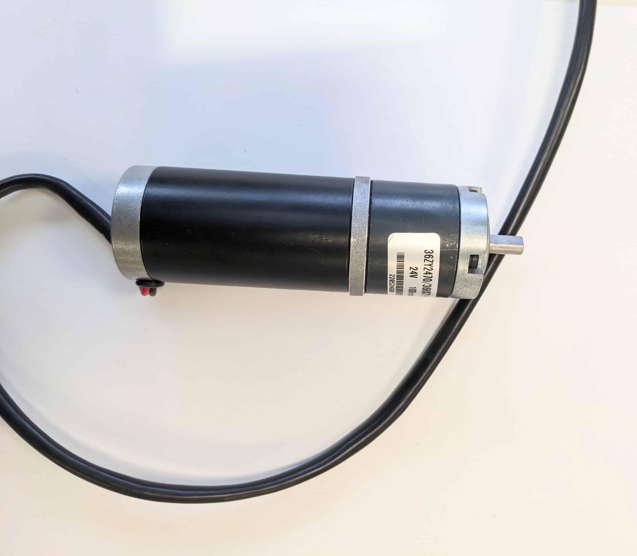
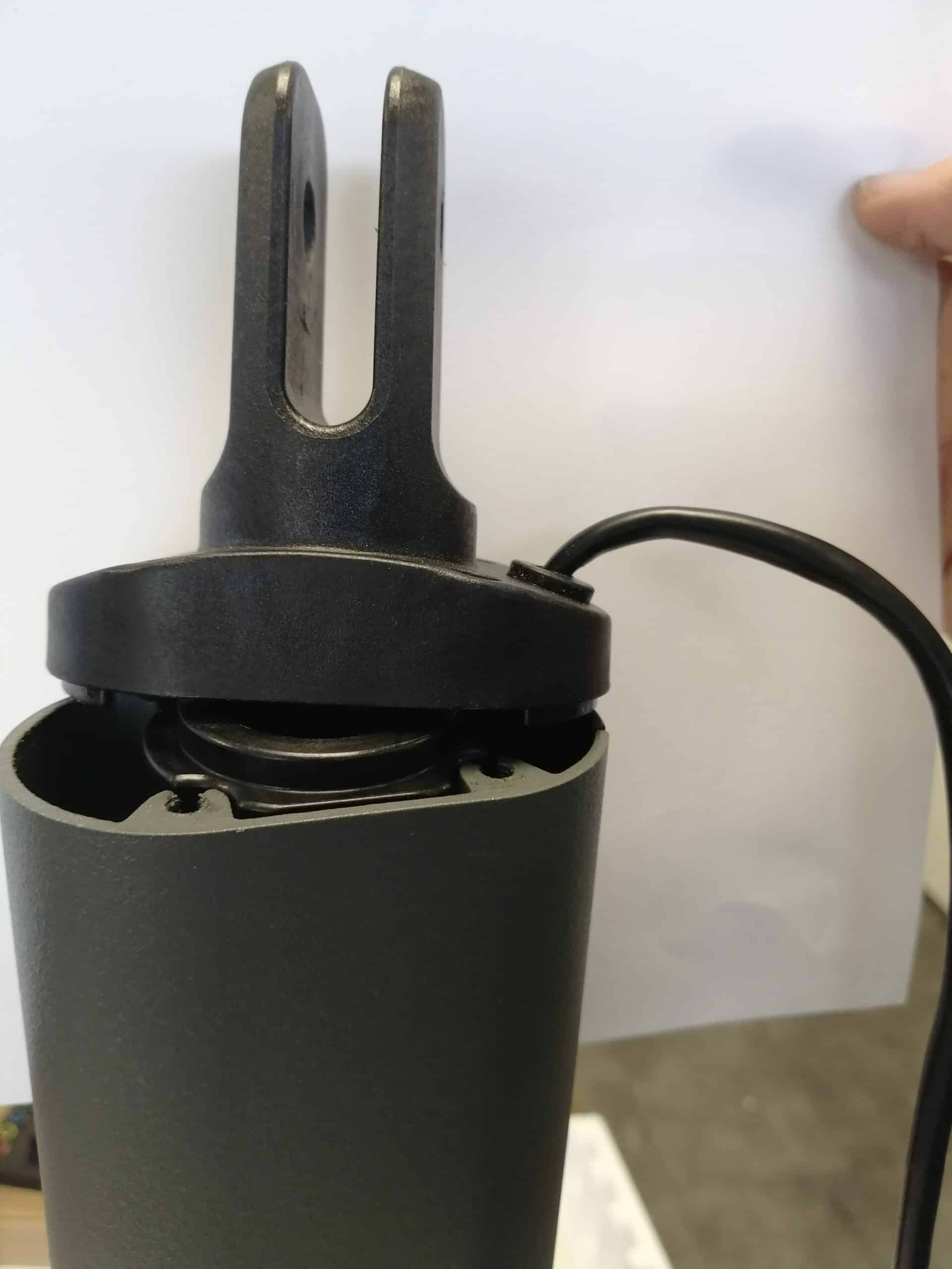
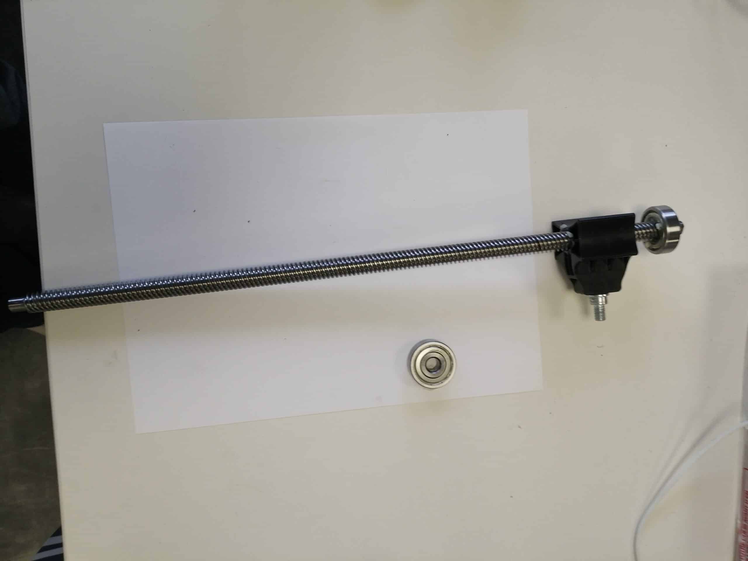
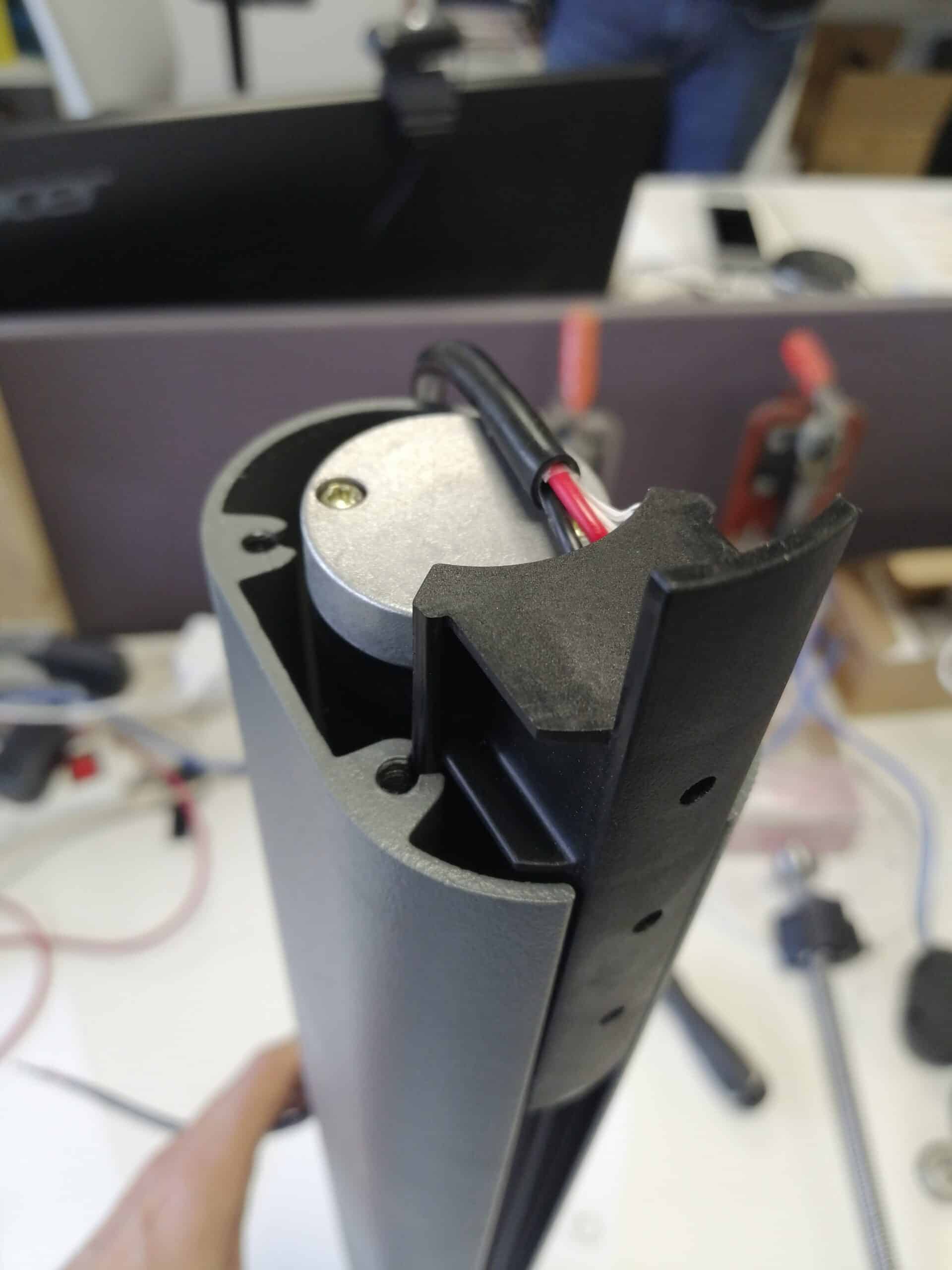
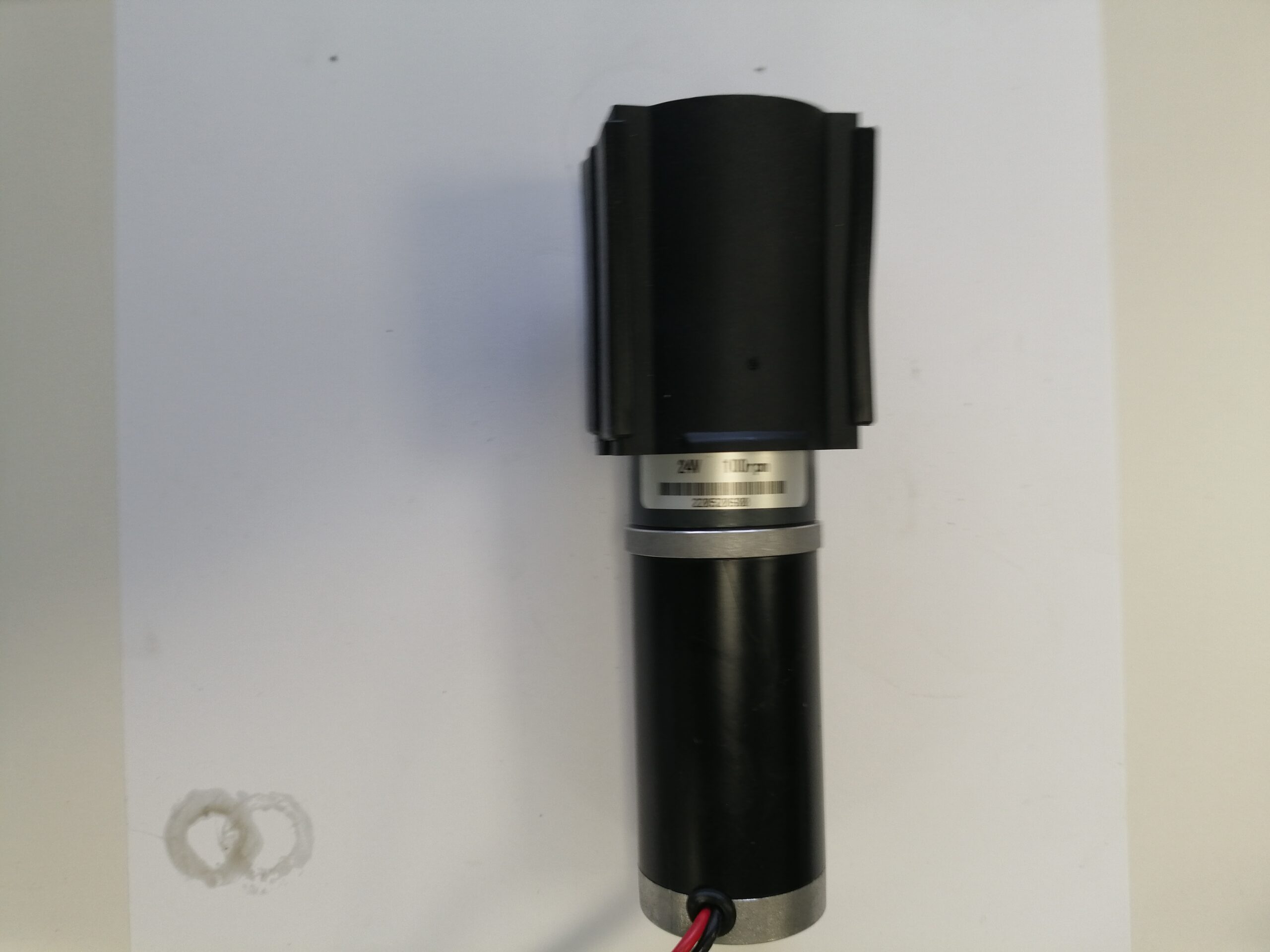
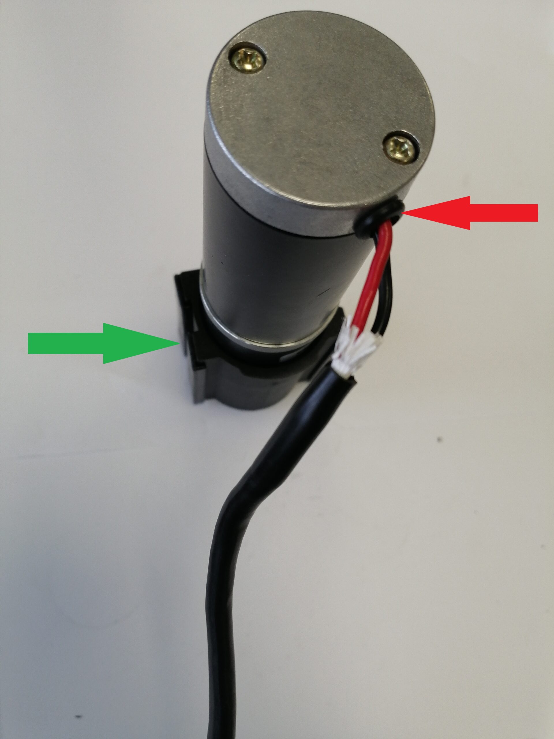
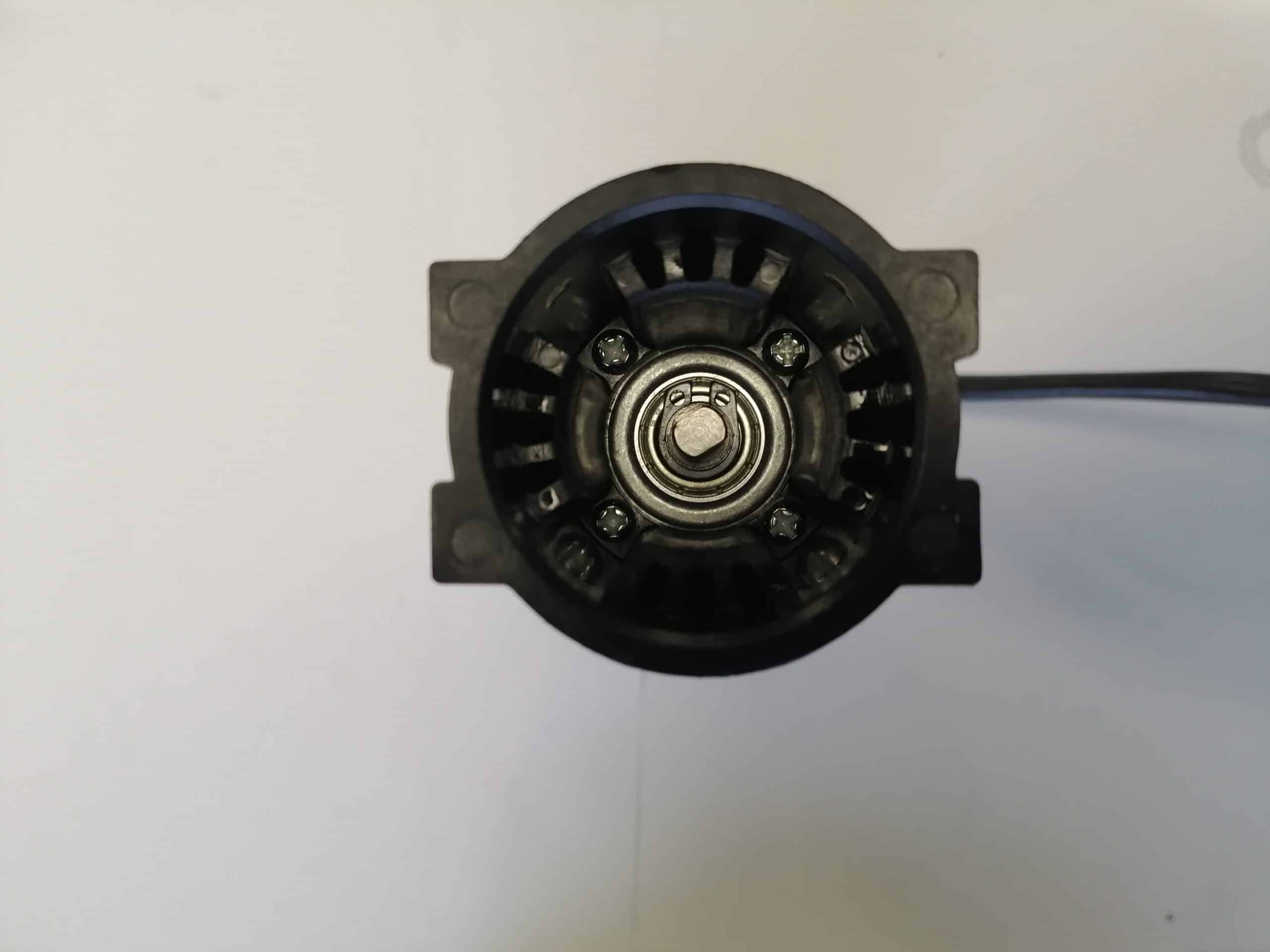
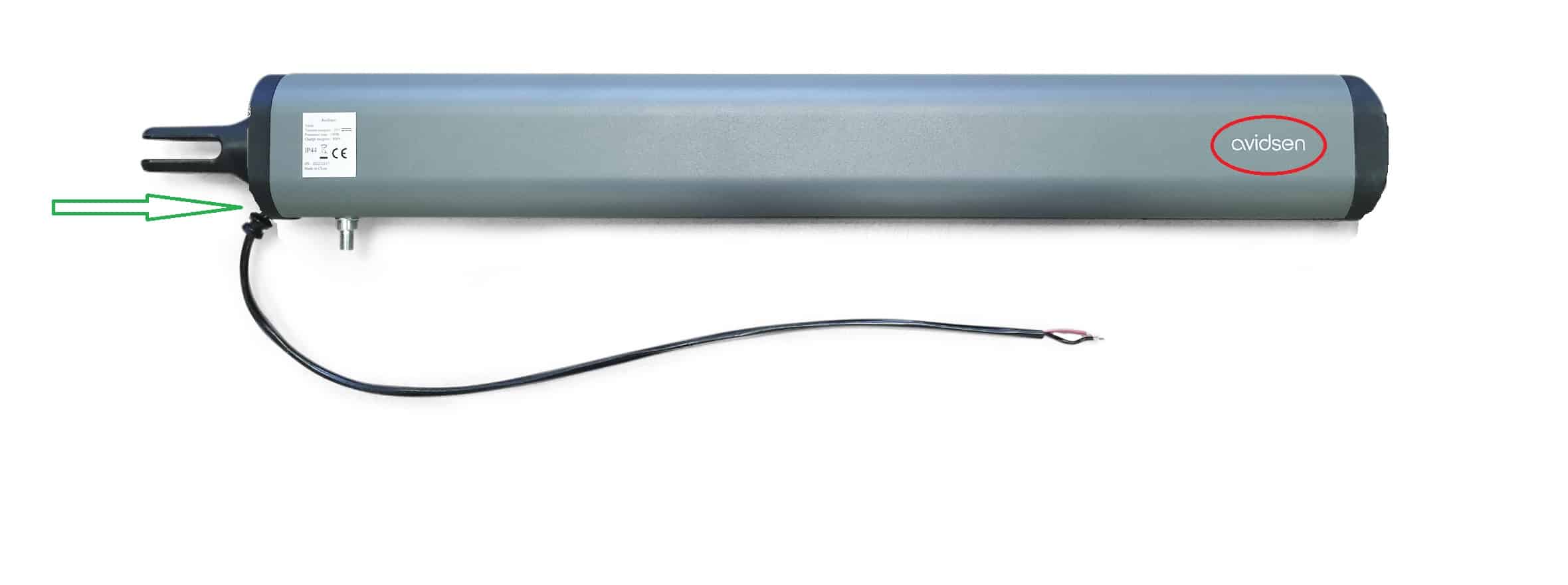
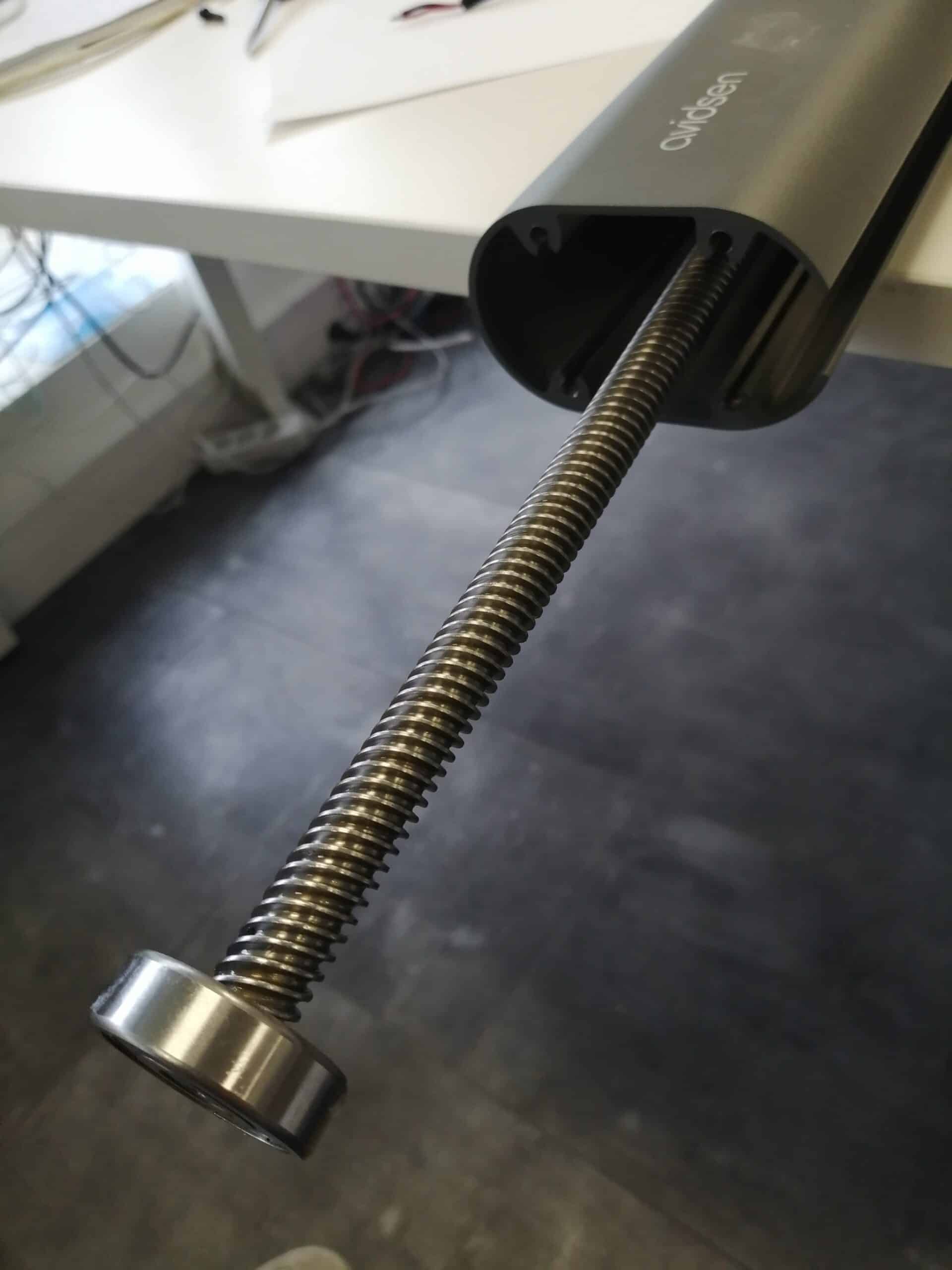
Your electric motor has stopped responding and you need to replace it. Follow the step-by-step instructions in this tutorial. The motor is delivered with its mechanical reduction system. Don't try to separate these two elements, as you risk losing internal components that will be very difficult to reassemble without damaging the whole unit. 
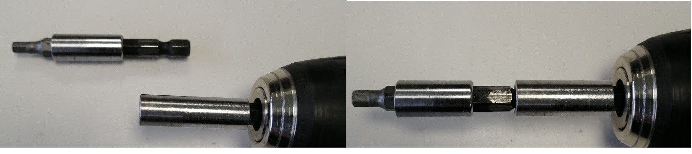
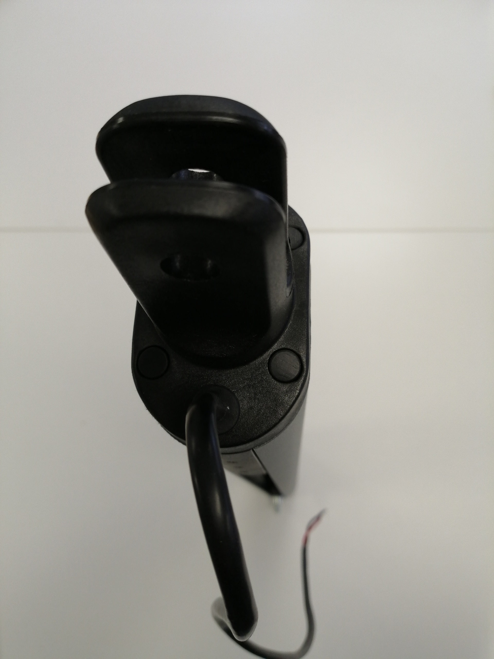
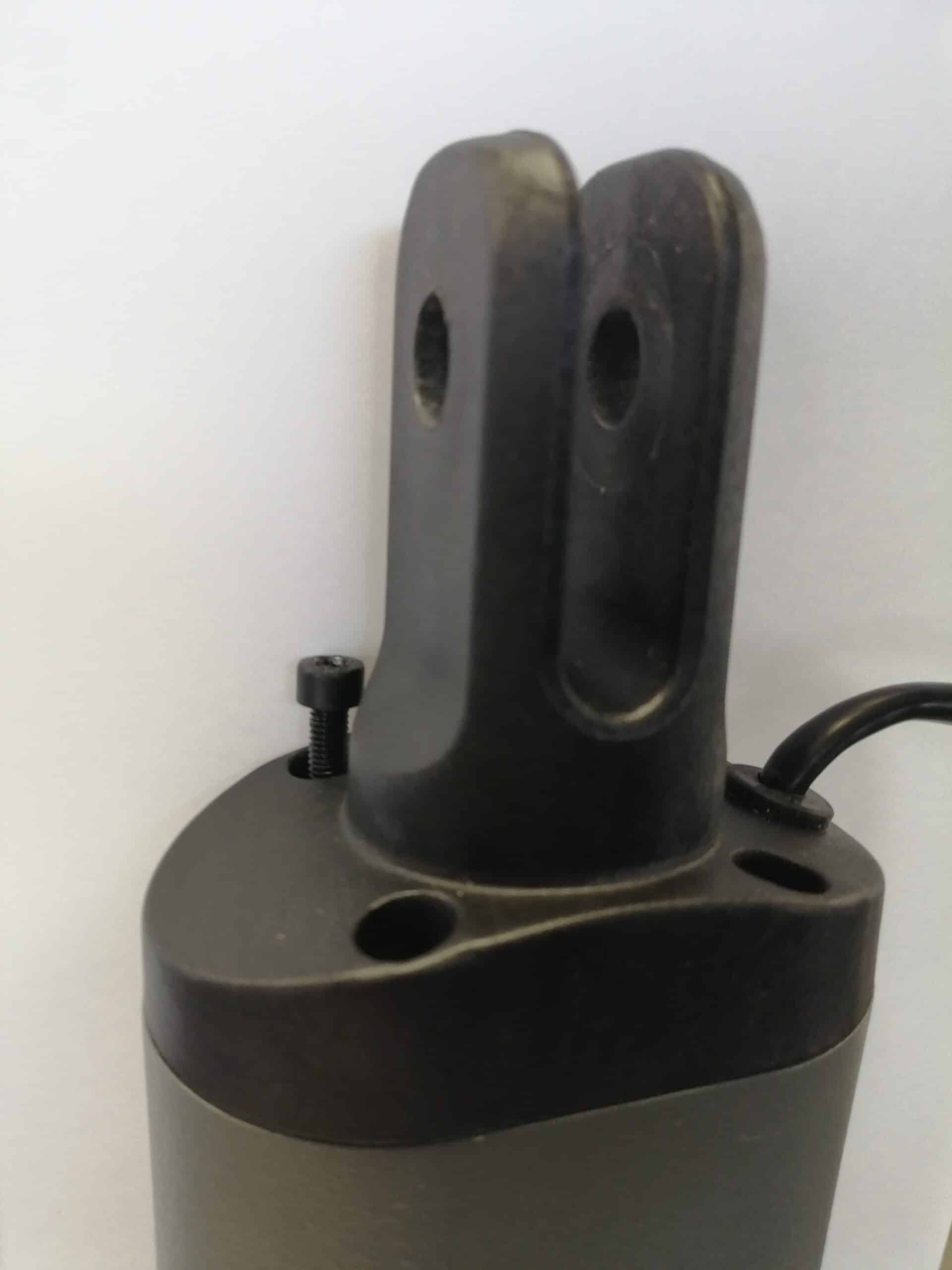
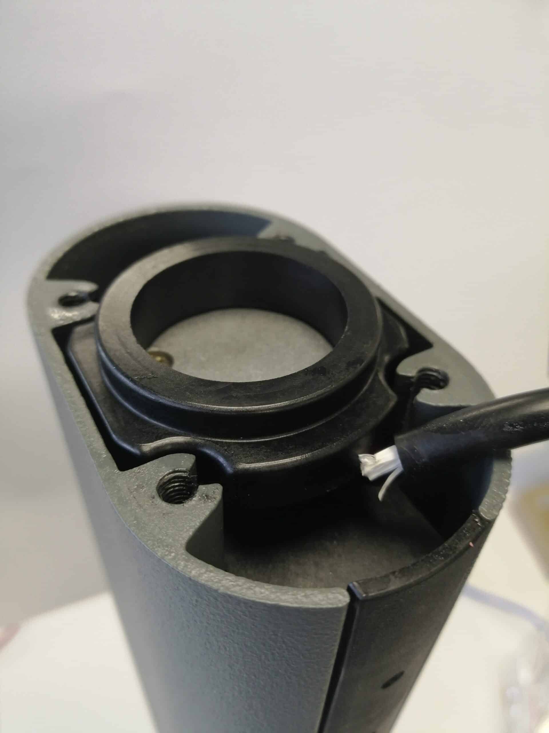
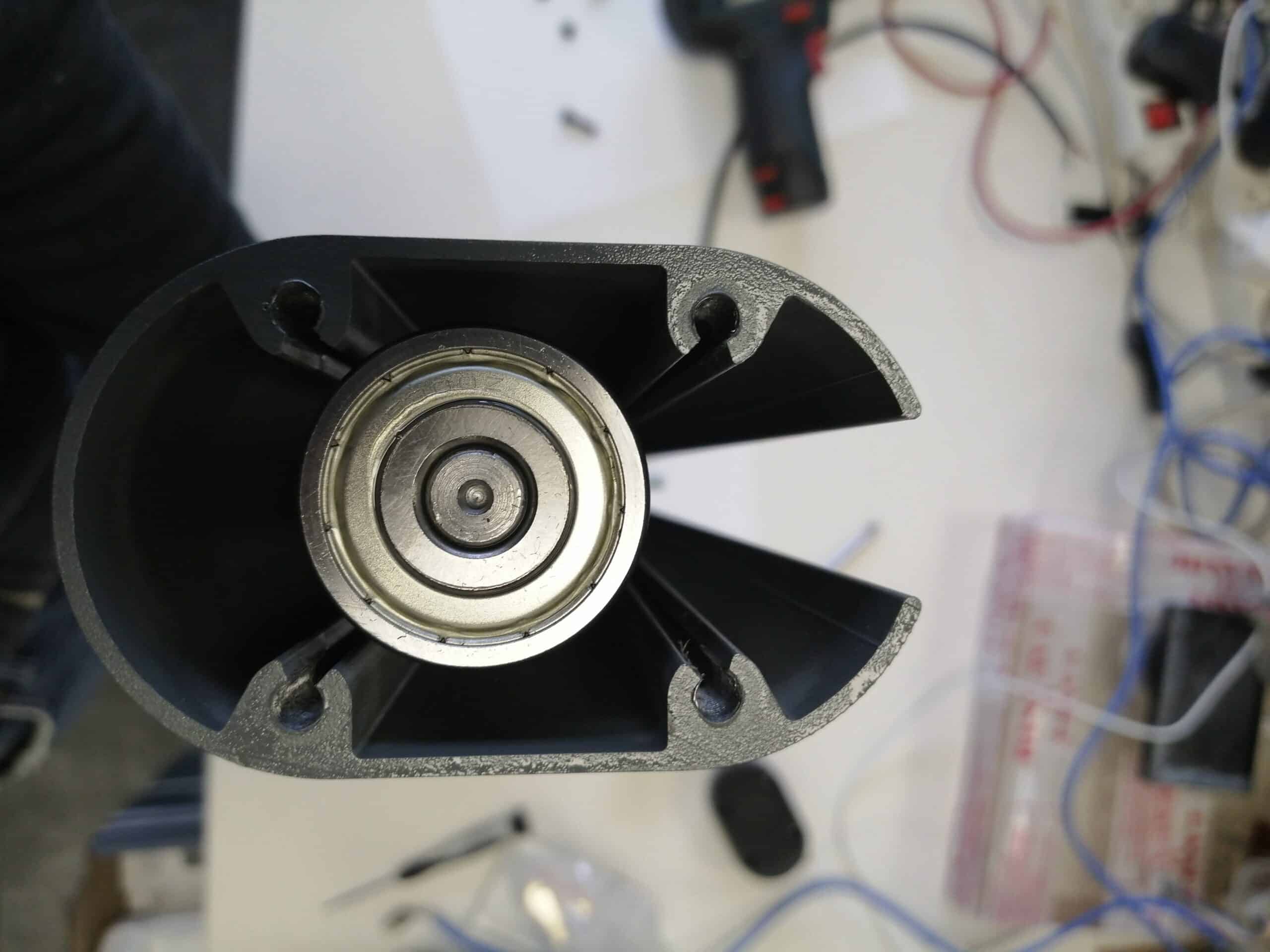
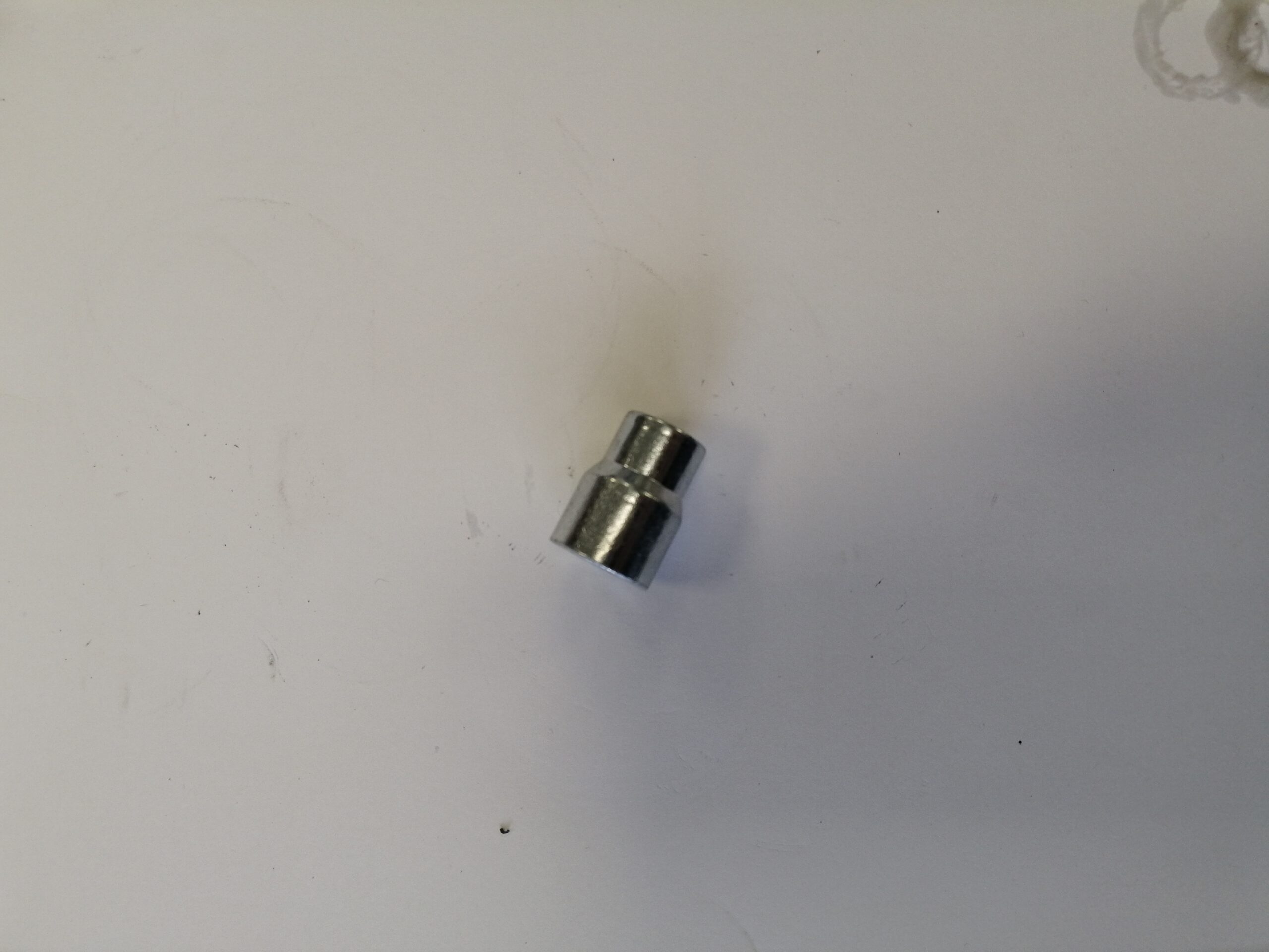
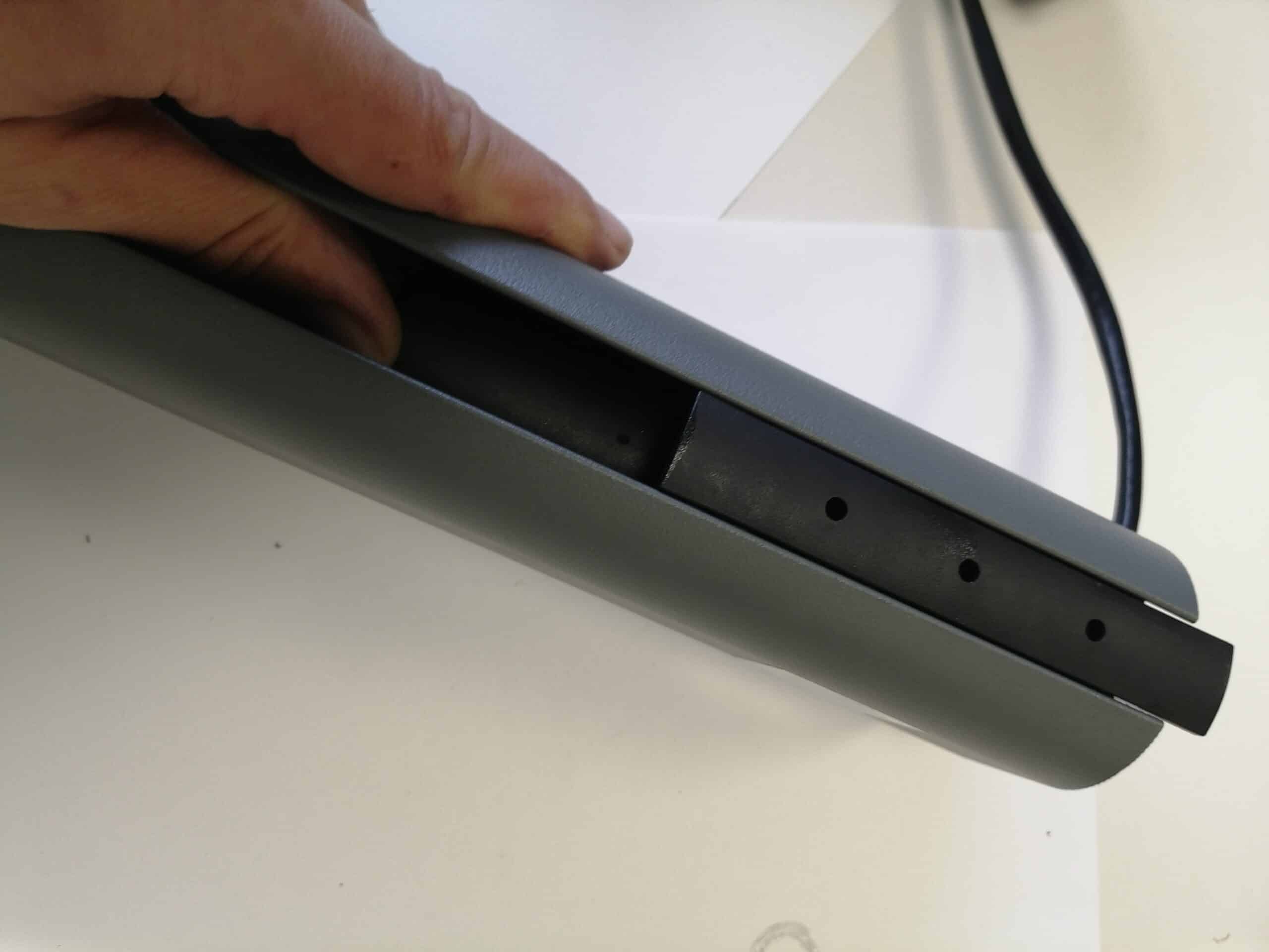
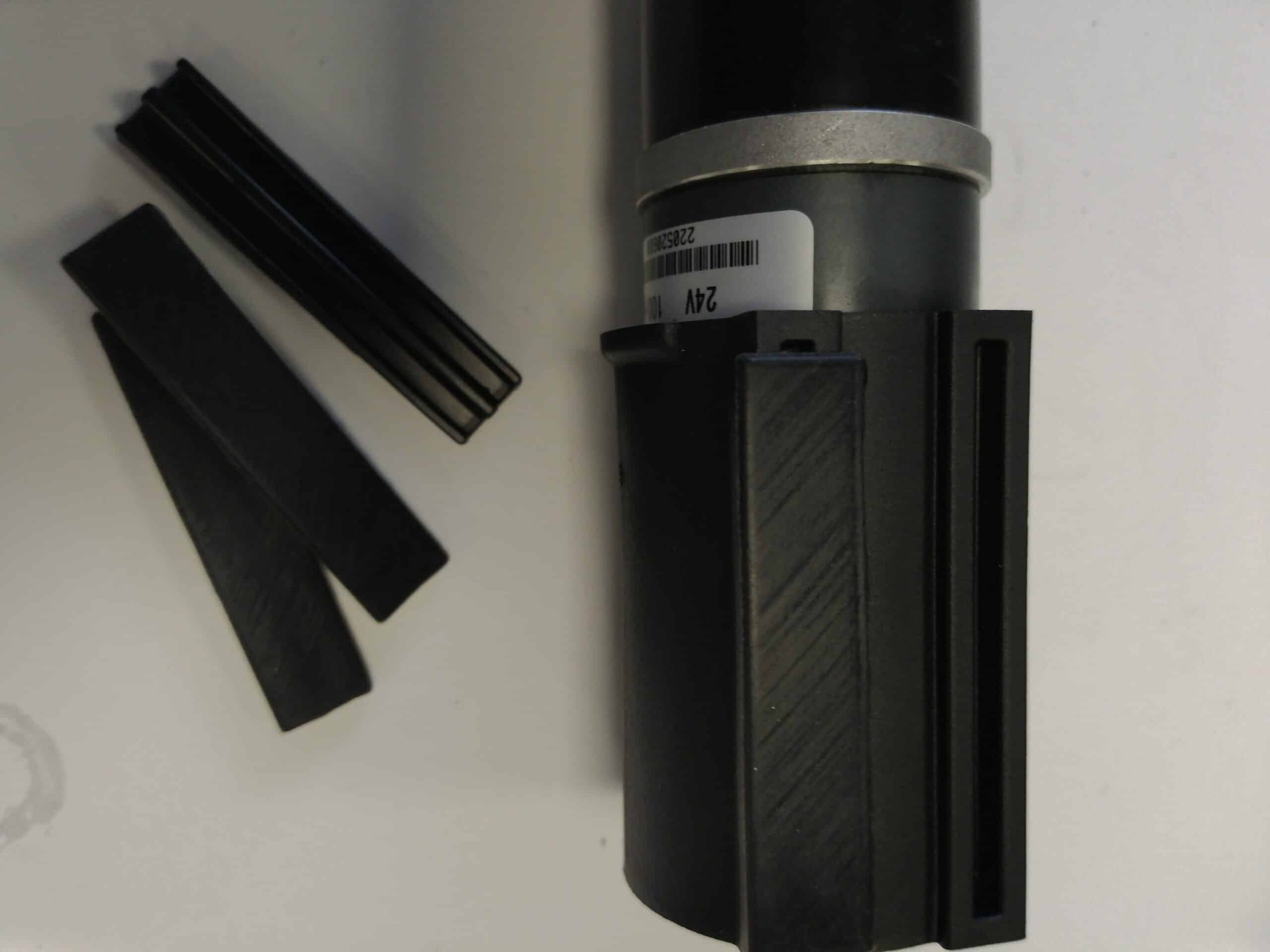
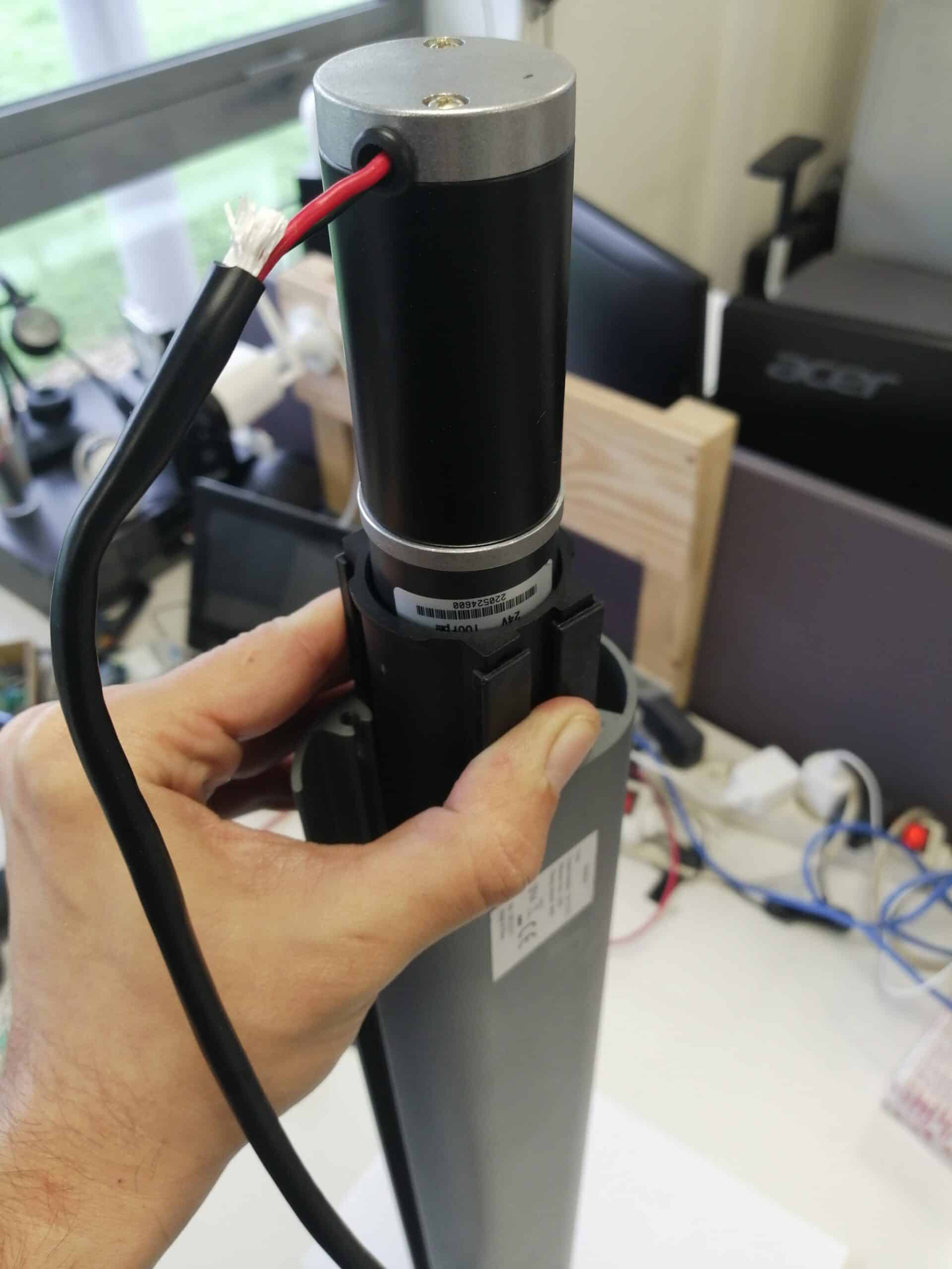
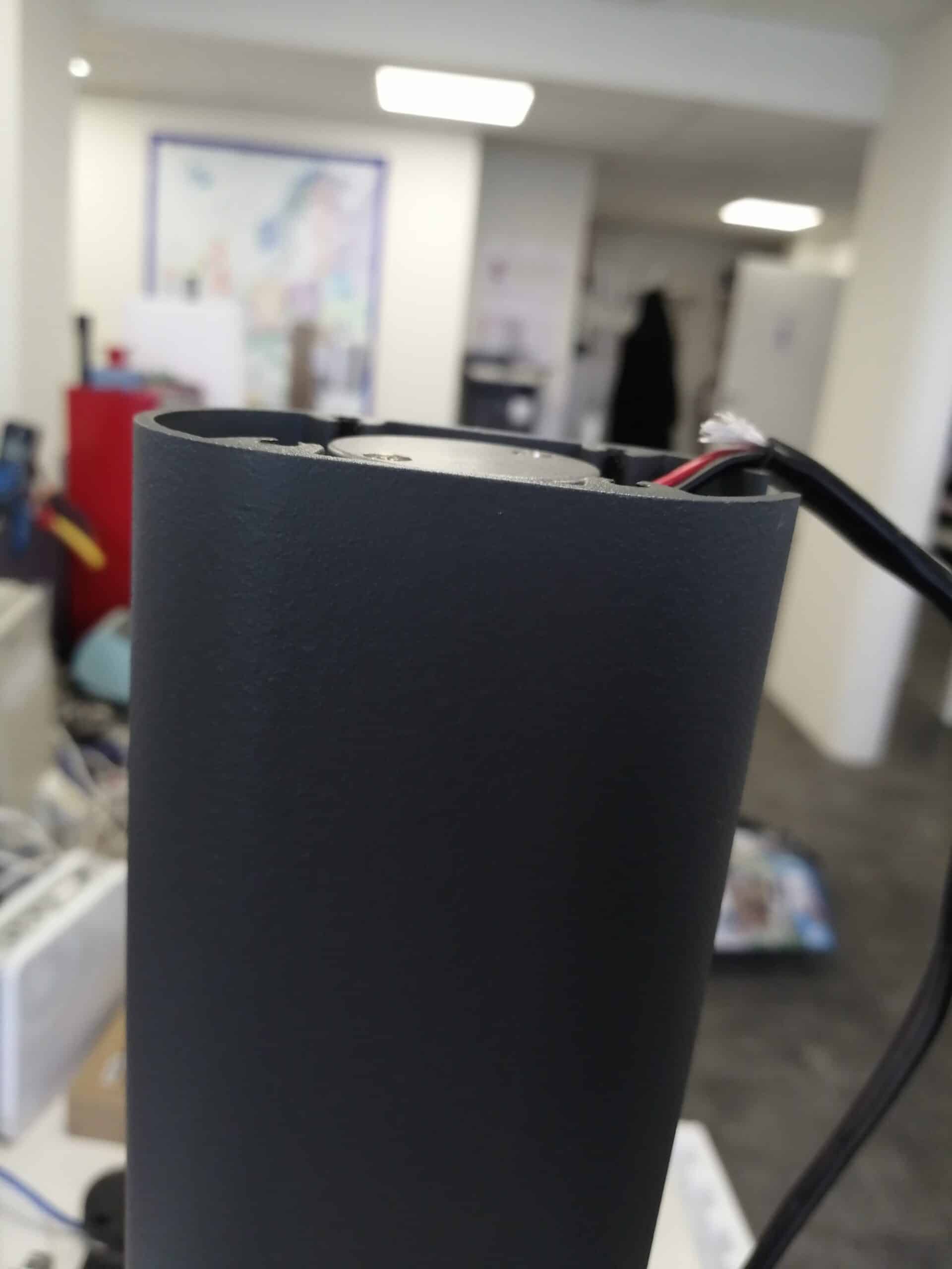
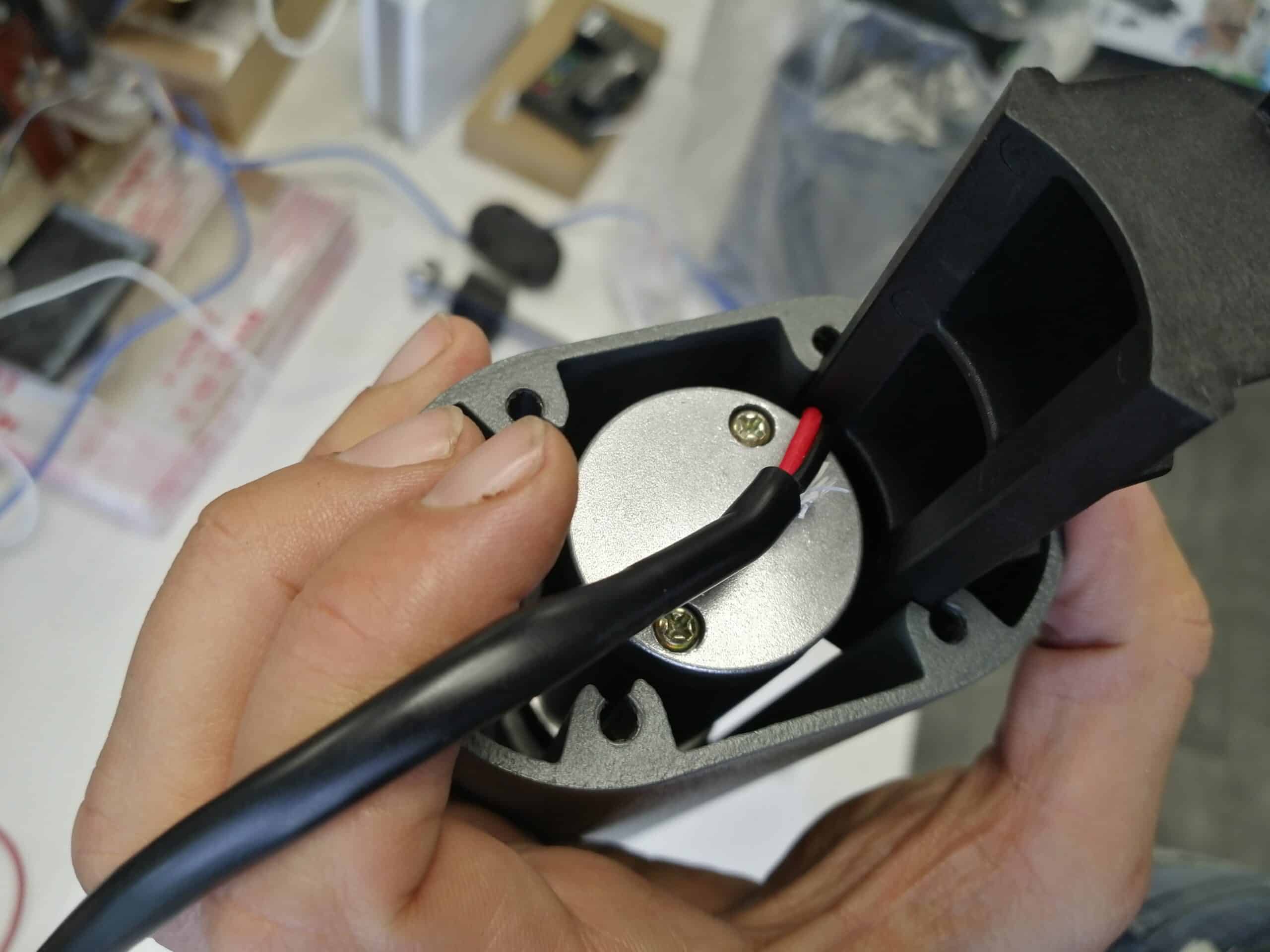
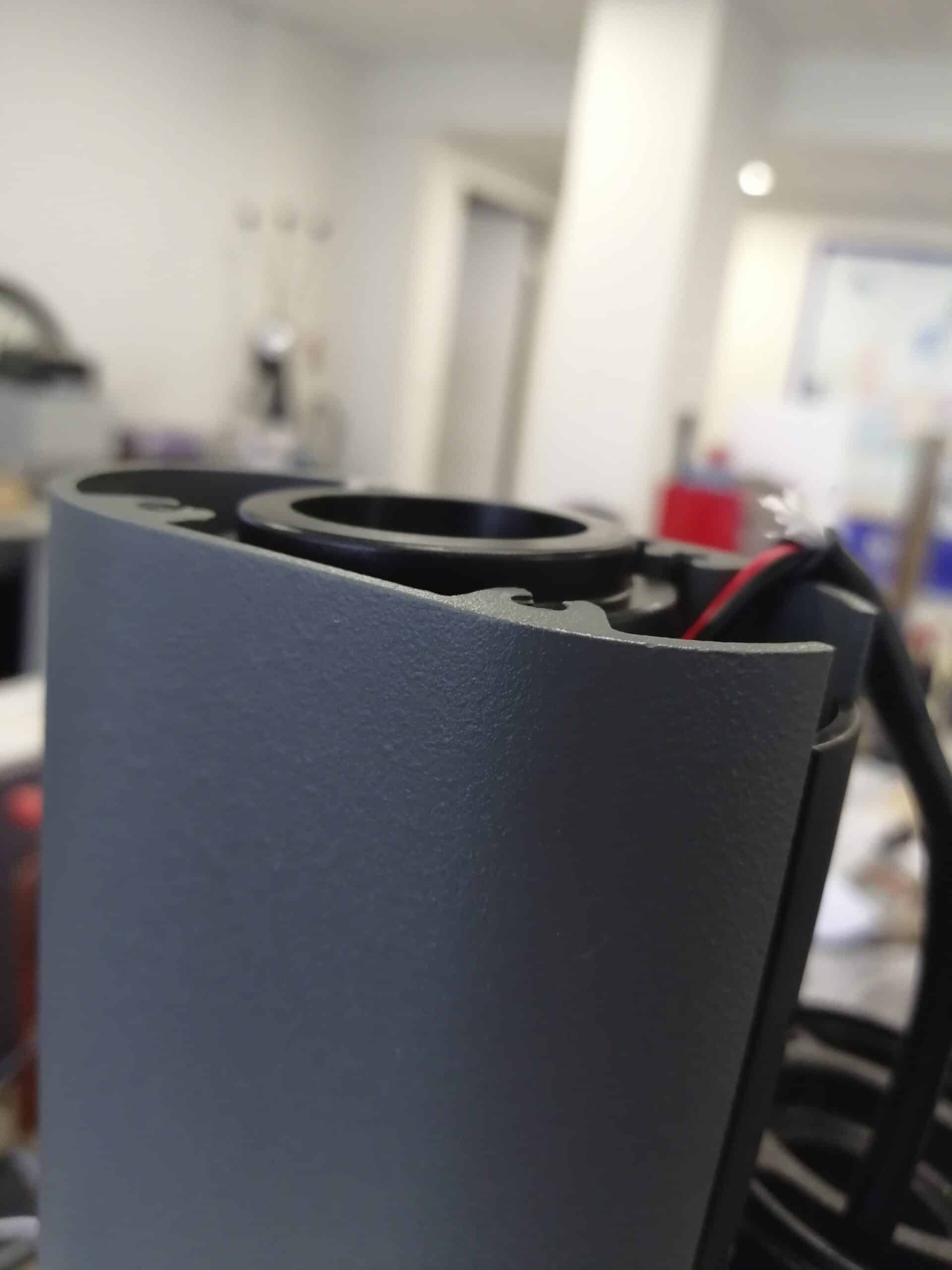
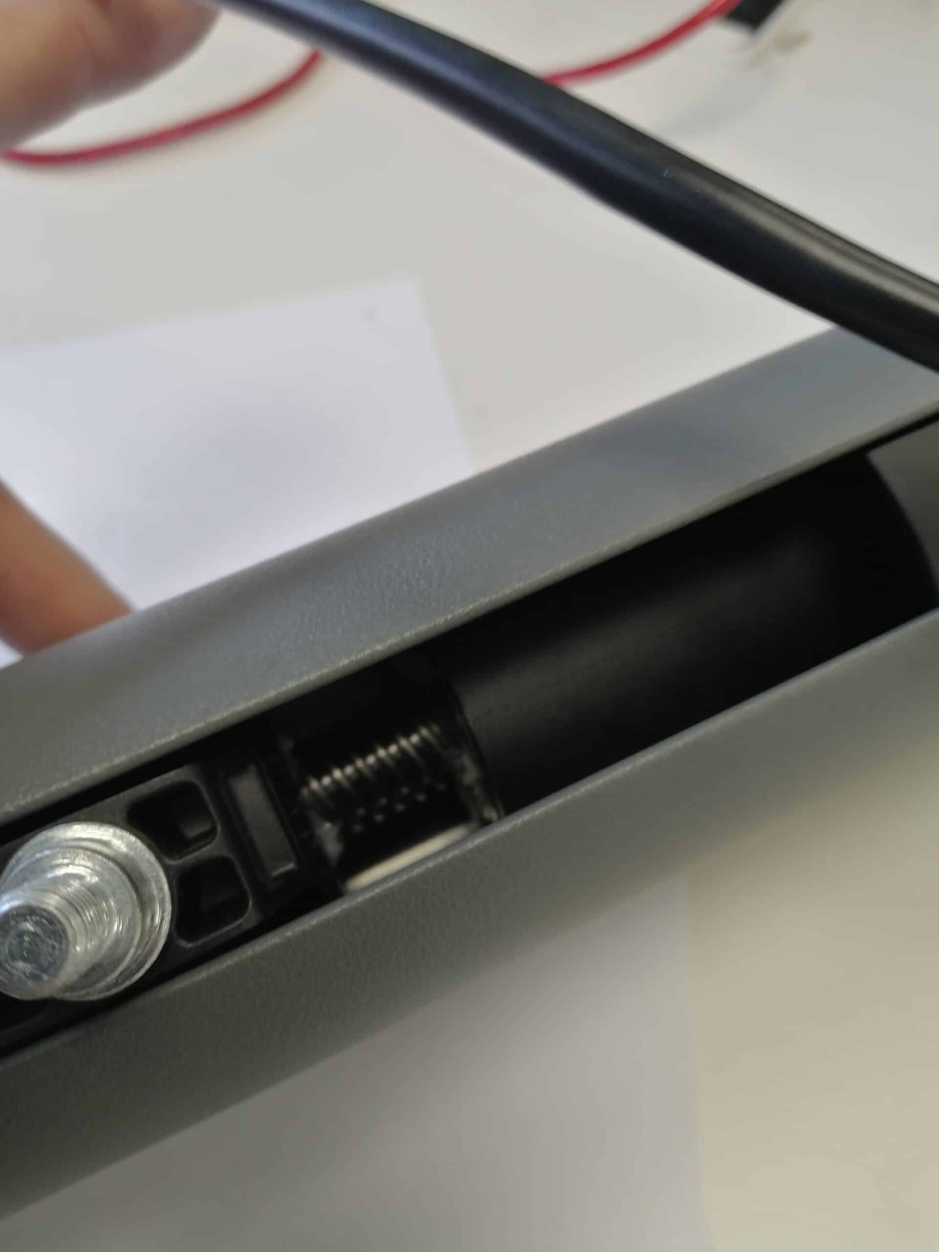
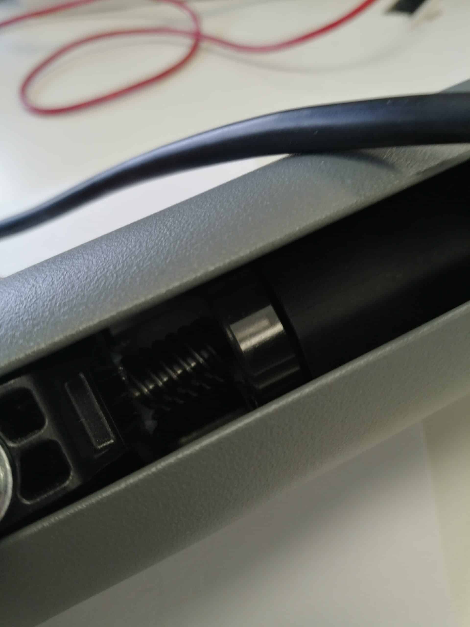
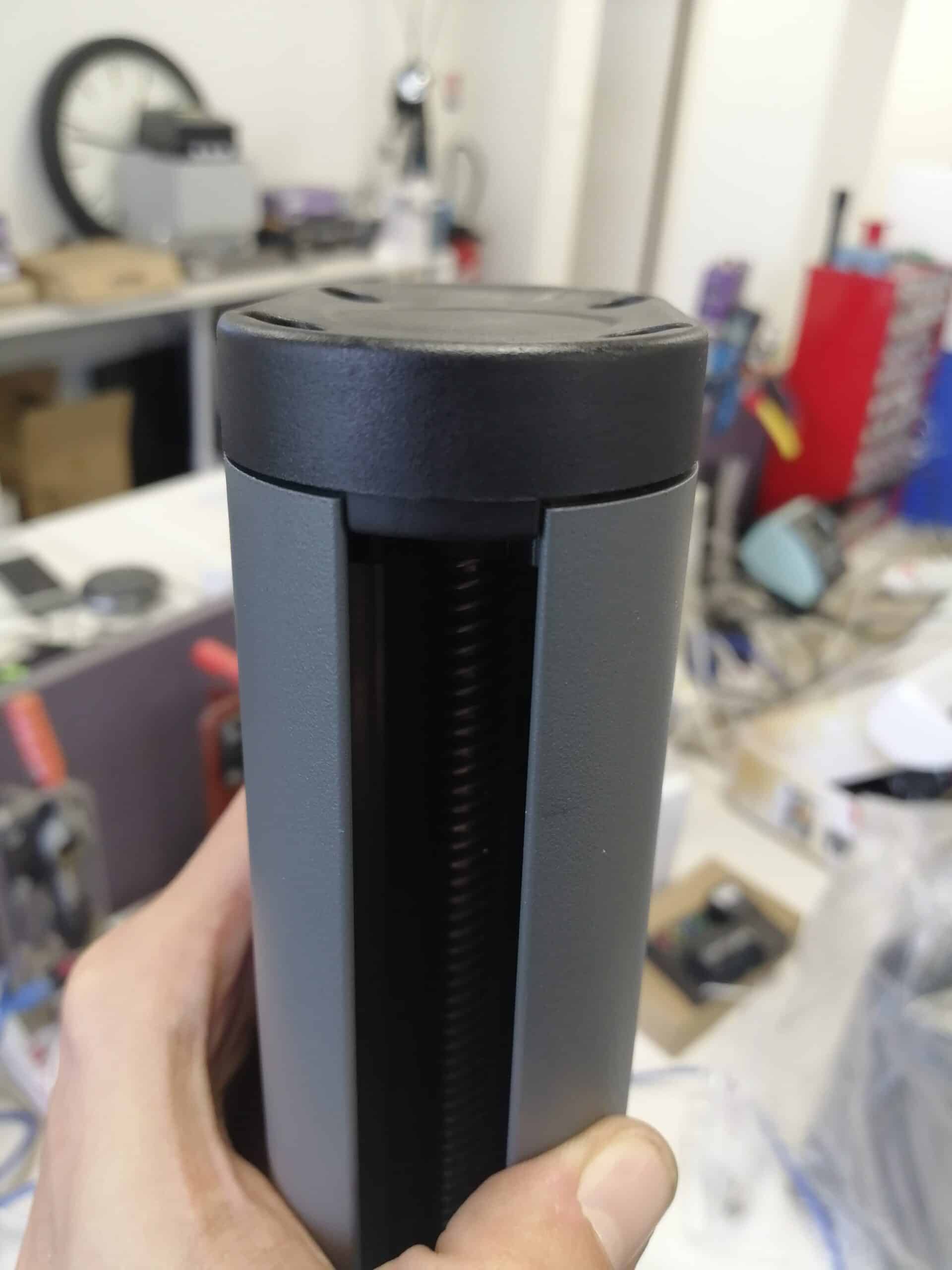
For simplicity's sake, it will be necessary to remove all internal components from the cylinder.

This tutorial is applicable for:

Avidsen - 114173 - Teha 410 / Avidsen - 114174 - Teha Connect / Avidsen - 114300 - Teha 320
Difficulté : Good handyman
Temps nécessaire : 25 minutes minutes
Nombre d’étapes : 24
Mise à jour : February 2025

Materials needed:

4″ BTR wrench or head, Phillips screwdriver

Tutorial steps:

Board

If you wish to use a screwdriver, assemble two bit extensions to gain access to the BTR screws at fork level, without having to present the BTR head askew and risk damaging the screw recess.

Step 1: Remove the protective rubbers from the rear forks

Remove the 4 protective rubbers from the screws.

Step 2: Unscrew the BTR screws

Unscrew and remove the 4 BTR screws.


Step 3: Remove the rear fork

Unhook the rear fork and remove it completely, passing it through the cable.

Step 4: Remove the black cap

Remove the black shim.

Step 5: Remove the protective rubbers and screws from the front panel

Remove the 4 protective rubbers and unscrew the 4 BTR screws to remove the front panel.

Step 6: Remove the front panel

Remove the front panel.

Step 7: Remove the worm screws

The worm screws can be accessed. Pull it out of the cylinder.

WARNING!

Do not lose the two ball bearings.

WARNING!

Don’t lose this link between the worm screws and the engine’s mechanical reduction system. It may end up on the worm screws or remain on the motor shaft. Expect him to fall on the next stage.

Step 8: Push the motor

Push the motor towards the rear of the cylinder.

The motor will be hard to pull out. This is due to the presence of rubber blades which help to keep it stable in the cylinder. If necessary, use a screwdriver to help you push it out.

Step 9: Remove the bottom cover

Once the motor is sufficiently extended, remove the lower black plastic cover, taking care to raise the motor cables to allow it to pass through.

You can then pull from the motor head to continue removing the motor.

Step 10: Remove the motor

The motor is out.

Board

To avoid losing them, before replacing the motor, remove the 4 rubber plates from the motor mount.

Step 11: Remove the motor support fixing screws

Unscrew and remove the 4 small Phillips screws.

Step 12: Remove the electric motor from the bracket

Separate the electric motor from its support.

You can scrap the electric motor and use the new one from the next step.

Step 13: Assemble the electric motor on the bracket

Replace the new motor on the bracket. Make sure that the motor wire (arrow red) is on the bottom right-hand side during final reassembly.

Check its position in relation to the locations of the rubber blades (arrow green) which will be located on the sides of the motor.


Step 14: Mount the electric motor on the bracket

Then tighten the screws to connect the bracket to the motor.

Step 15: Replace the rubber blades

Replace the rubber blades on the motor mount.

Step 16: Put the motor back into the cylinder

Press the rubber blades firmly into the cylinder frame, and push it inwards

Board

(No effect other than aesthetic) Be sure to identify the direction of the cylinder before inserting the motor. It must be opposite the “Avidsen” marking on the cylinder.

Step 17: Position the motor in the cylinder

Push the motor flush with the cylinder frame.

Step 18: Replace the bottom cover

Replace the bottom cover, taking care to raise the motor cable to allow it to pass through.

Step 19: Replace the black shim

Reposition the black shim.

Step 20: Adjust motor depth

Push the shim flush with the cylinder frame.

Step 21: Refitting the rear fork

Pass the motor fork back through the cable.

Screw it back onto the motor housing and replace the rubber covers.

Board

Hold the cable gasket securely on the fork to prevent it coming out when refitting the fork.

WARNING!

Replace the link between worm screws and the electric motor on worm screws before carrying out the following operations.

Step 22: Insert the worm screws

Insert the worm screws into the cylinder and push it all the way to the motor.

Step 23: Fit the worm screws into the motor

The worm screws bearing must fit into the motor mount so that the link on the worm screws integrates the motor shaft.

Lightly push the worm screws and check that the bearing fits properly.


WARNING!

If the bearing does not retract, this means that the motor shaft is not in the same position as the worm screws.

Turn the worm screws slightly while pushing it inwards.

Board

Before reinstalling the front panel, power the motor with a 9V or 12V battery, and check that the carriage runs smoothly when opening and closing.

Step 24: Replace the front panel

Replace the front of the cylinder. Remember to place the notch towards the cart’s circulation hole on the worm screws.

Tighten the screws and replace the rubber covers.


END

Congratulations, you’ve replaced your electric jack motor and it’s ready to operate your gate leaves again.

Keep in touch
Youtube Linkedin

Follow us on social networks

About Avidsen
  • Who are we?
  • Contact
  • Who are we?
  • Contact
Support
  • Avidsen Technical Support
  • Extel brand technical support
  • Philips technical support
  • Thomson Technical Support
  • Avidsen Technical Support
  • Extel brand technical support
  • Philips technical support
  • Thomson Technical Support
Avidsen group brand
  • Avidsen Brand
  • Extel Brand
  • Philips Brand
  • Thomson Brand
  • Avidsen Brand
  • Extel Brand
  • Philips Brand
  • Thomson Brand
Copyright 2025 © All rights reserved Avidsen
  • Legal Notice
  • Personal data protection policy
  • Terms and Conditions of Use
  • Legal Notice
  • Personal data protection policy
  • Terms and Conditions of Use
Thank you for your rating!
Thank you for your rating and comment!
This page was translated from: French
Please rate this translation:
Your rating:
Change
Please give some examples of errors and how would you improve them: