Skip to content
  • English
    • French
    • Italian
    • Spanish
    • German
    • Dutch
    • Portuguese (Portugal)
    • Greek
    • Polish
  • English
    • French
    • Italian
    • Spanish
    • German
    • Dutch
    • Portuguese (Portugal)
    • Greek
    • Polish
Logo Avidsen
  • Products
    • Products
    • Avidsen Brand
    • Extel Brand
    • Philips Brand
    • Thomson Brand
  • Support
    • Tutorials on repair and use
    • Avidsen Technical Support
    • Extel brand technical support
    • Philips technical support
    • Thomson Technical Support
  • The Group
    • The Group
    • Contact
  • Ethic Company
  • Where to buy ?
\

How to take electrical measurements on solar kit 114375

  1. Home
  2. How to take electrical measurements on solar kit 114375

How to take electrical measurements on solar kit 114375

In this tutorial, we will look at the measurement points to be carried out in order to check that the solar kit Avidsen 114375 is working properly.

This tutorial is applicable for:

Avidsen - 114375 - Universal solar kit for gate motorisation
Difficulté : Good handyman
Temps nécessaire : 10 minutes
Nombre d’étapes : 8
Mise à jour : April 2025

Tutorial steps:

REMINDER

You will find opposite the terminal correspondences on the MPPT board of the solar kit

REMINDER

See connection for a list of batteries for use with the current range of 24V engines.

Step 1: Measure voltage solar panel

Take a multimeter and set it to measure voltage (Vdc). If you have a multimeter with a gauge, set the dial to 200V.

Prerequisite:

Solar panel: Connected

Batteries: Connected

Position the multimeter probes on the SOLAR IN input on the MPPT board.

Connect the red probe (V) to SOLAR IN + and the black probe (COM) to SOLAR IN -.

  • Check that the value displayed on the multimeter is positive (no – displayed to the left of the reading).

Correct the polarity of connection panel if necessary.

  • Expected voltage (variable according to sunshine): Maximum 45VDC

If the voltage displayed is around 5V, panel is not producing enough energy to charge the batteries. Check the orientation and sunlight of panel. The battery charging current is 0mA. The batteries will not be charged.

Disconnect the solar panel from the MPPT board and measure the voltage on the wires coming from panel.

  • Expected voltage (variable according to sunshine): Maximum 45VDC

Step 2: Measure the short-circuit current of the solar panel

Take a multimeter and set it to measure current (A)

Position the red probe on the multimeter’s 10 A input.

Prerequisite:

Solar panel: Disconnected

Measure either at panel or on the wires arriving at the MPPT board, positioning one probe per wire.

Expected current (variable according to sunshine): Maximum 500mA

Then reconnect the solar panel to the MPPT board.

Step 3: Measuring battery voltage

Take a multimeter and set it to measure voltage (Vdc). If you have a multimeter with a gauge, set the dial to 20V.

Prerequisite:

Batteries: Disconnected

Position the probes on each battery terminal.

Expected voltage: Between 12.1V and 13V

If the voltage is lower, the battery is malfunctioning.

If the battery is at 12V, connect a 12V device to the battery and check whether the voltage drops or remains stable.

Step 4: Measure charging voltage

Take a multimeter and set it to measure voltage (Vdc). If you have a multimeter with a gauge, set the dial to 200V.

Prerequisite:

Solar panel: Connected

Batteries: Disconnected

Set multimeter probes to BATTERY + and -.

Expected voltage: 27VDC

If you read 0V, the MPPT board has failed.


Step 5: Measure load current

Take a multimeter and set it to measure current (A)

Position the red probe on the multimeter’s 10 A input.

Prerequisite

Solar panel: Connected

Batteries: Connected

Motorization: Disconnected

Disconnect one of the battery terminals.


Position one probe on the free terminal, and the other probe on the free battery terminal.

Expected current (variable according to battery charge demand and sunshine): Between 50mA and 300mA approx.

If you don’t measure any current, the MPPT board is faulty.

If the current varies (increase or decrease), it’s just that the MPPT board is calculating the best charging current.

Step 6: Measure motor output voltage

Take a multimeter and set it to measure voltage (Vdc). If you have a multimeter with a gauge, set the dial to 200V.

Prerequisite:

Batteries: Connected

Position the sensors on the MOTORIZATION output terminals of the MPPT board.

Expected voltage: 27VDC

If you measure 0V, the MPPT board is out of order.

To check that the connection between the MPPT board and the actuator is correct:

Position the probes on the metal fins of the connector (for AVLO Battant 24V boards)

Expected voltage: 27VDC

If you measure 0V, check the connection between the MPPT board and the connector.

Step 7: Measuring PCB consumption

Take a multimeter and set it to measure current (mA).


Prerequisite

Batteries: Connected

Motorization: Plug-in

Disconnect one of the battery terminals.


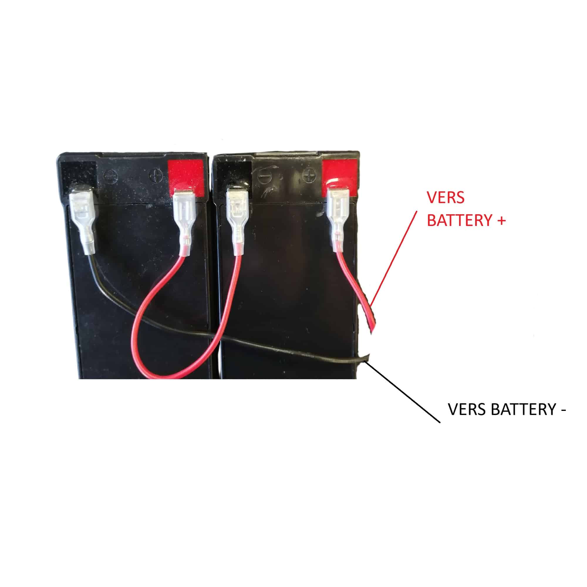
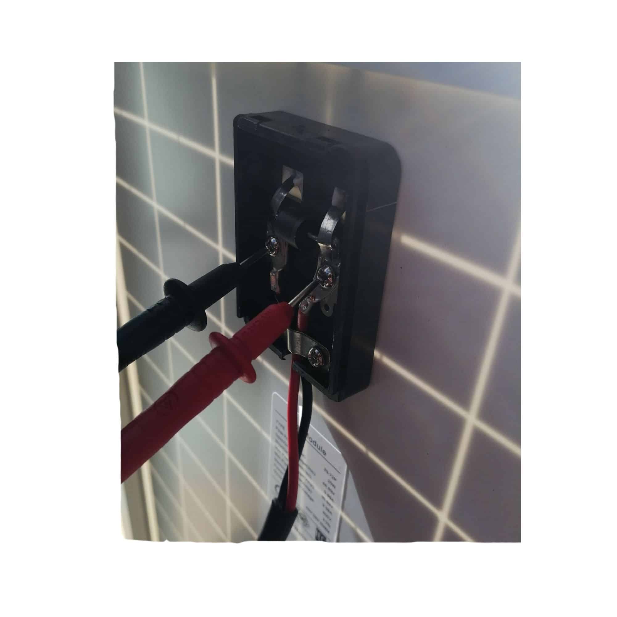
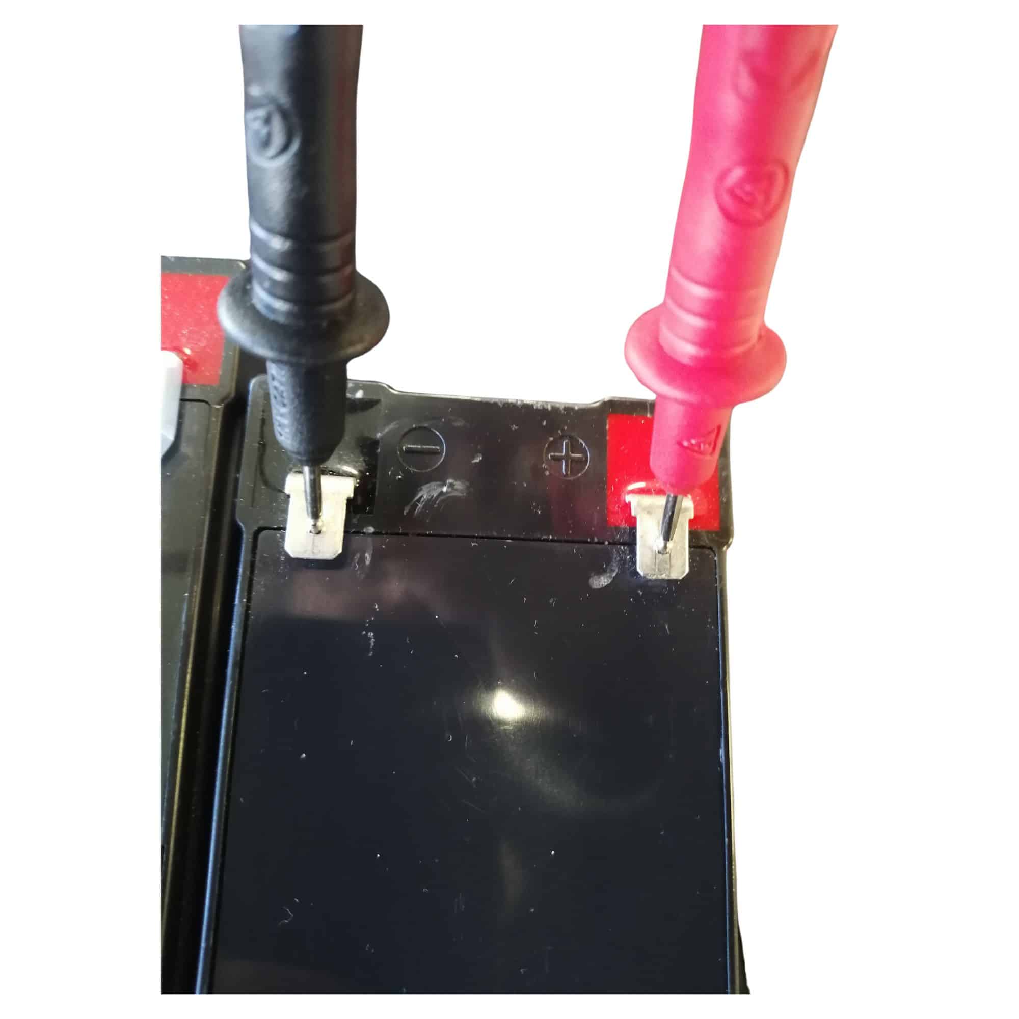
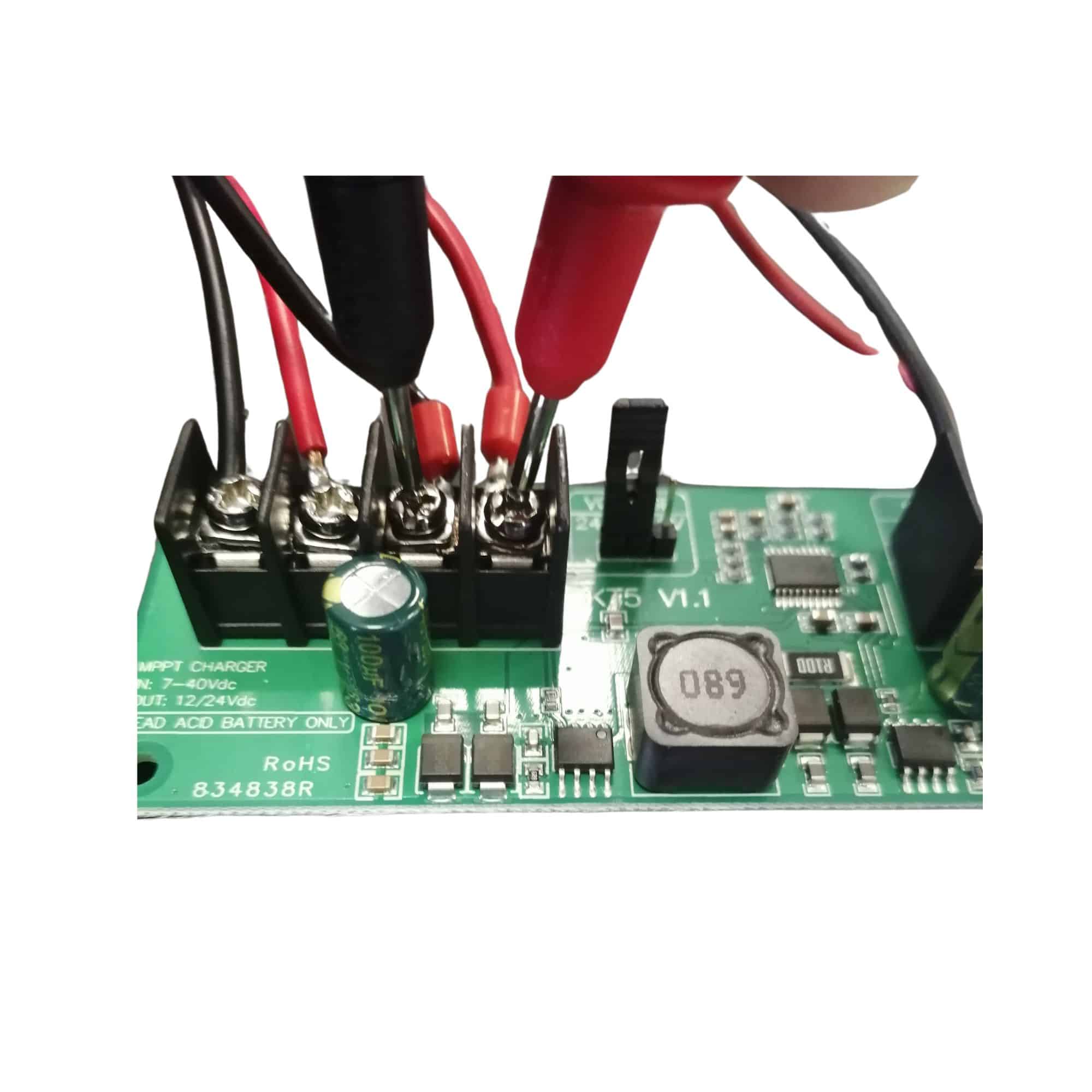
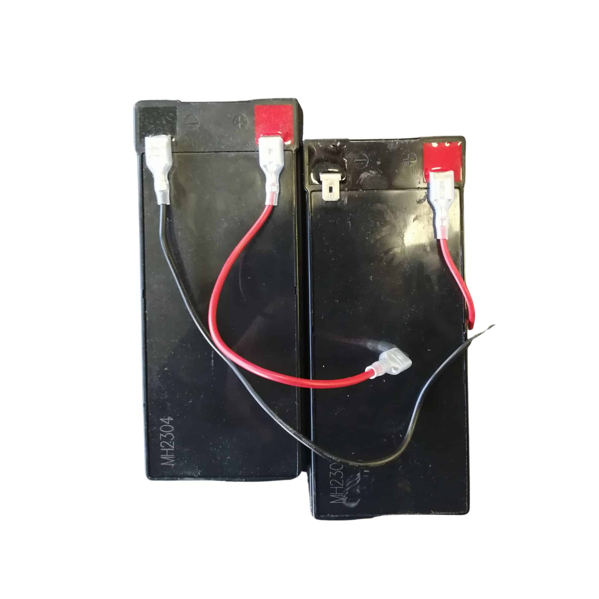
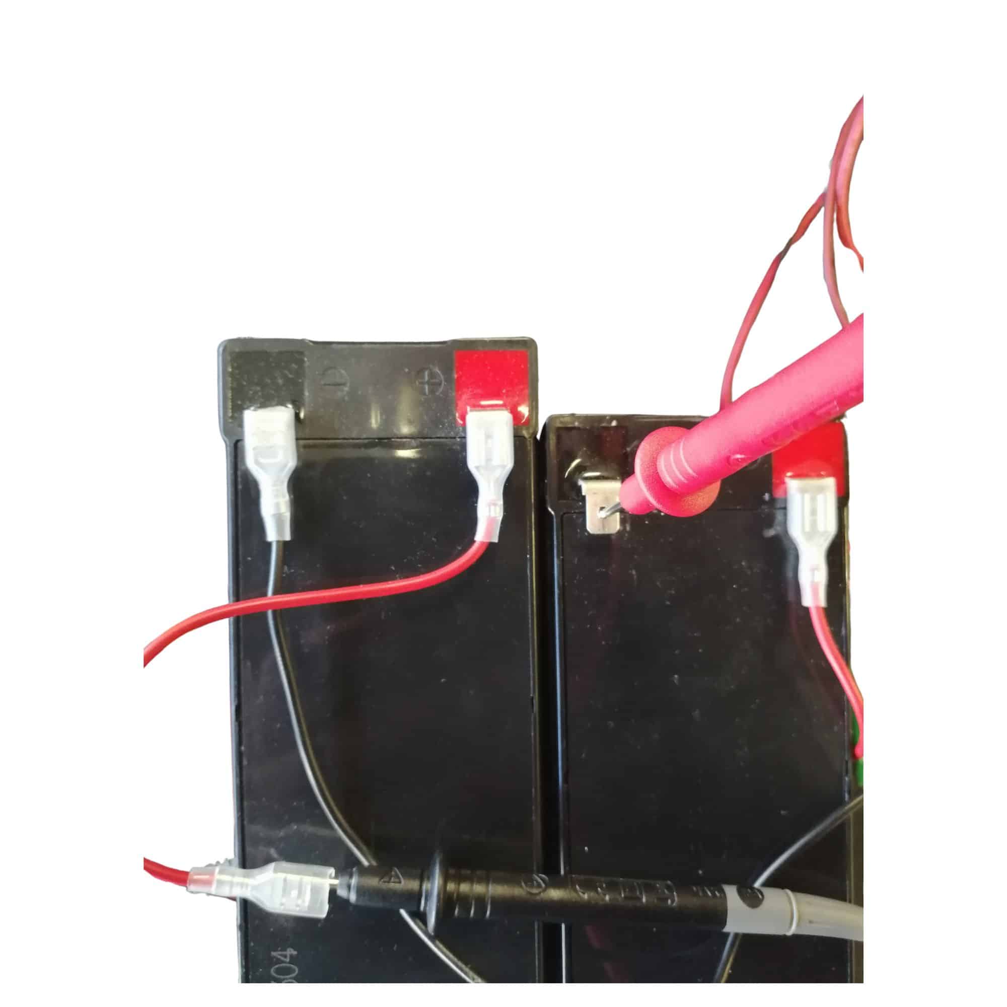
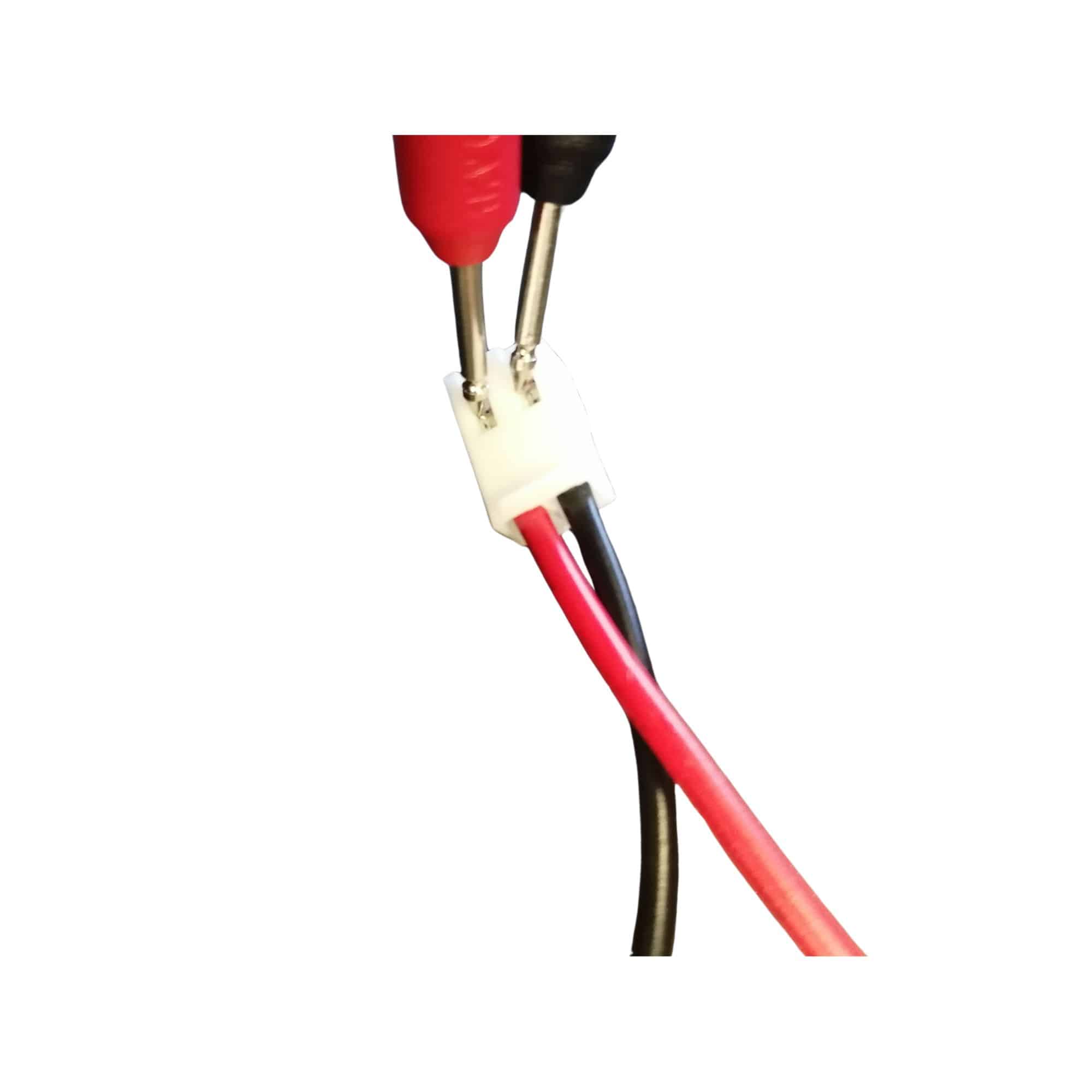
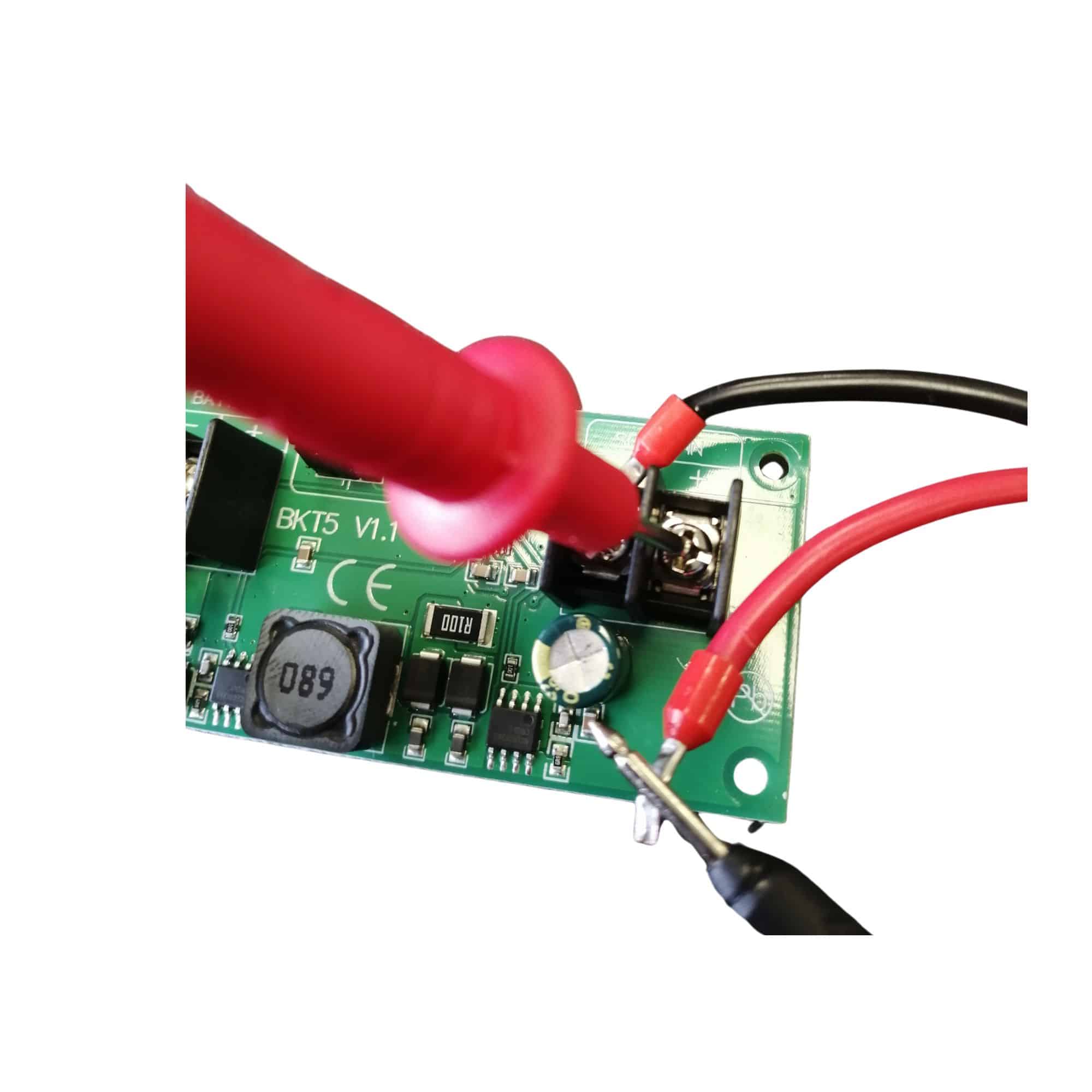
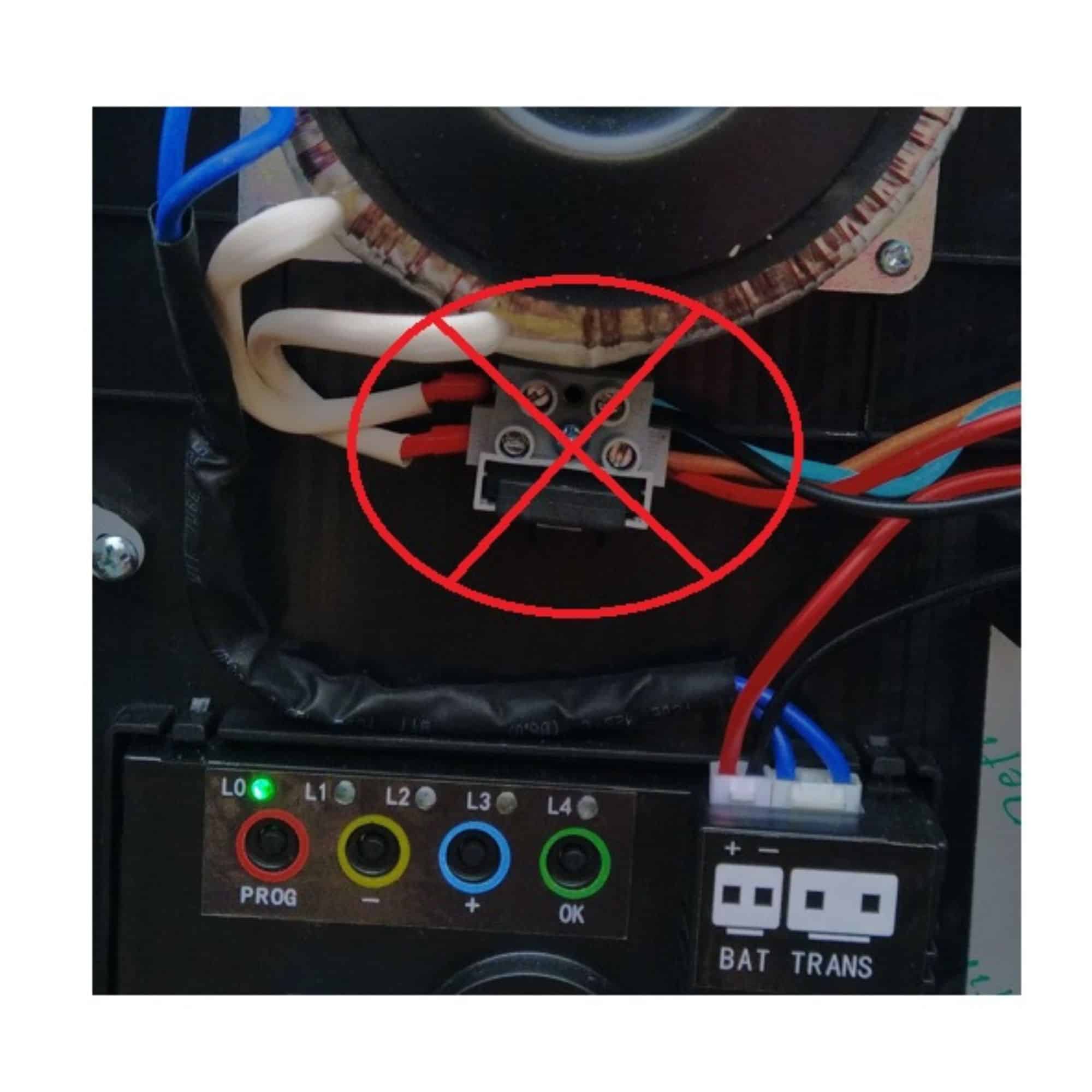
Place one probe on the free terminal, and the other probe on the free battery terminal.
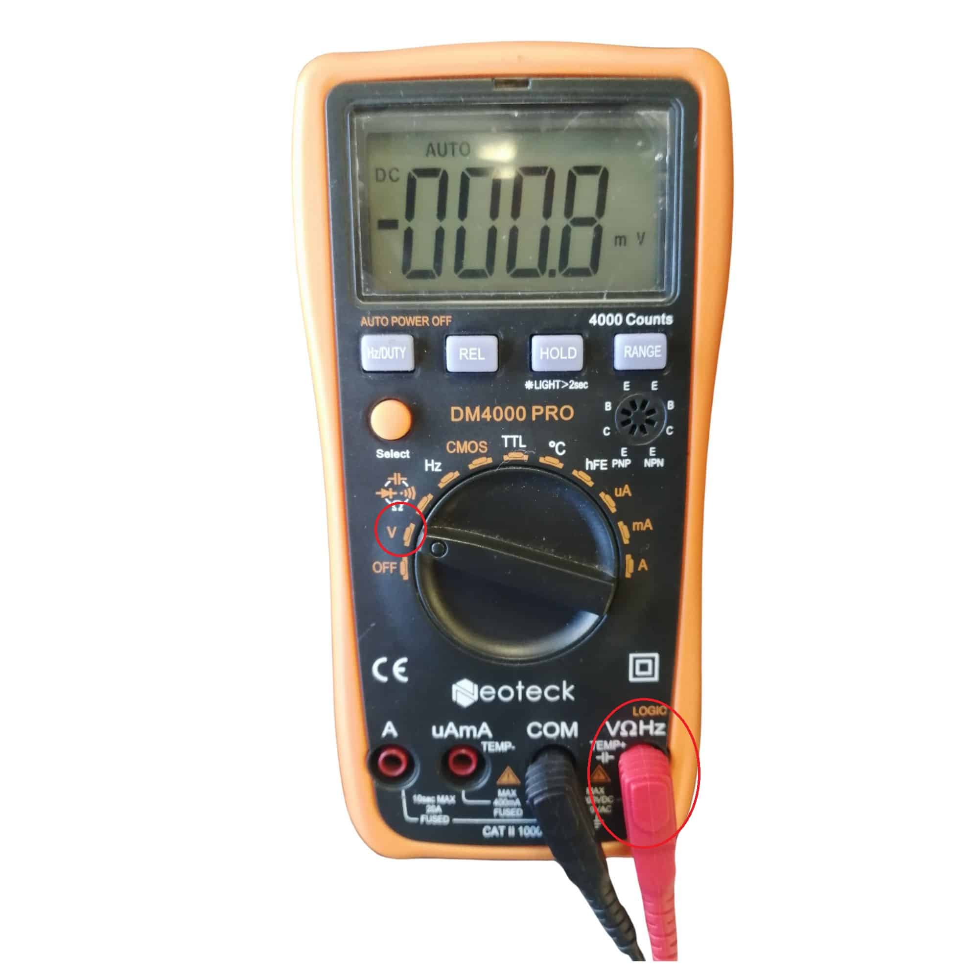
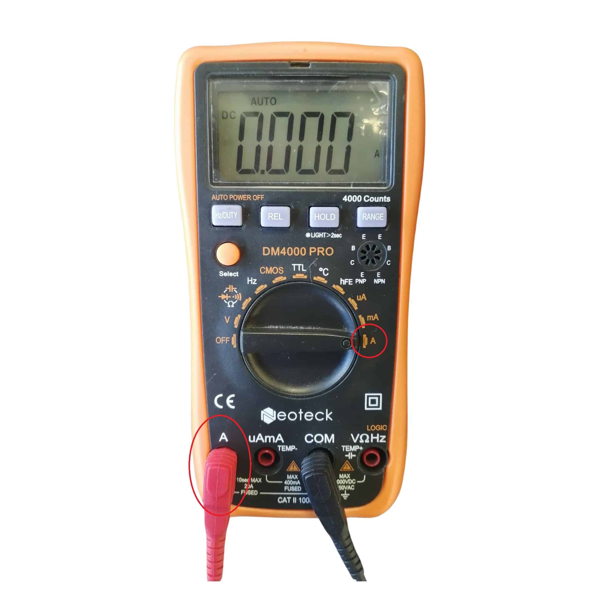
Current expected:

  • AVLO Folding 24V card

Card in standby mode but without motor movement (green light on): 42mA

Card in standby (green LED off): 3.2mA

  • Card CA2B9SL Sliding 24V

Card in standby mode but without motor movement (green light on): 35mA

Card in standby mode (green LED off): 2mA

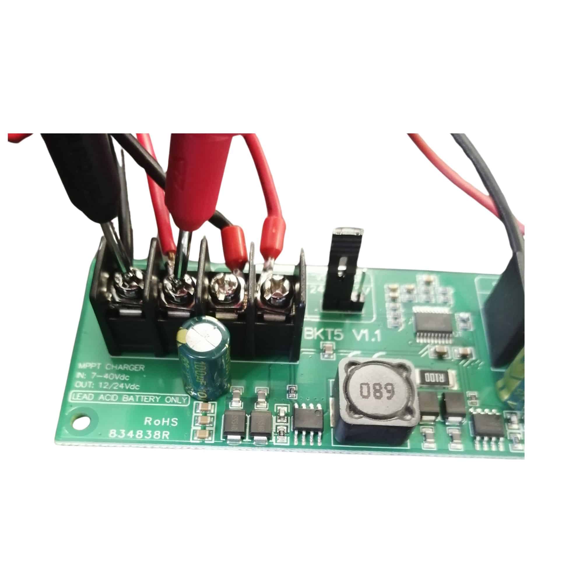
If the current value rises briefly, it’s because the electronic board has picked up a 433.92MHz radio signal during measurement.


Step 8: Measure MPPT board consumption

Take a multimeter and set it to measure current (mA).


Prerequisite:

Solar panel: Connected

Batteries: Disconnected

Motorization: Disconnected

Disconnect the red wire from SOLAR IN

Position one multimeter probe on the red origin wire of solar panel, and position the other multimeter probe on the SOLAR IN + terminal of the MPPT board

Expected current: 8mA

If the current is 0mA, the MPPT board is out of order.


WARNING!

Under no circumstances should the transformer’s fuse holder be used to make the connection between the solar kit and the gate operator.

Otherwise a permanent discharge current will flow through the transformer coil, discharging the batteries prematurely.

WARNING!

panel must be south-facing (south-west to a lesser extent).

solar panel must be inclined at 30°.

The sun must strike solar panel directly. On overcast days, the load will be much lower, or even zero, depending on cloud cover.

If there is even partial shade at solar panel, the batteries will not be charged.

MAINTENANCE

Regularly clean the solar panel with a soft, dry cloth

Regularly check battery voltages.

recommended Batteries should be recharged with a dedicated charger before the onset of winter, and sometimes during if you notice a loss of speed.

Batteries must be disconnected from the solar kit when recharging.


Keep in touch
Youtube Linkedin

Follow us on social networks

About Avidsen
  • Who are we?
  • Contact
  • Who are we?
  • Contact
Support
  • Avidsen Technical Support
  • Extel brand technical support
  • Philips technical support
  • Thomson Technical Support
  • Avidsen Technical Support
  • Extel brand technical support
  • Philips technical support
  • Thomson Technical Support
Avidsen group brand
  • Avidsen Brand
  • Extel Brand
  • Philips Brand
  • Thomson Brand
  • Avidsen Brand
  • Extel Brand
  • Philips Brand
  • Thomson Brand
Copyright 2025 © All rights reserved Avidsen
  • Legal Notice
  • Personal data protection policy
  • Terms and Conditions of Use
  • Legal Notice
  • Personal data protection policy
  • Terms and Conditions of Use
Thank you for your rating!
Thank you for your rating and comment!
This page was translated from: French
Please rate this translation:
Your rating:
Change
Please give some examples of errors and how would you improve them: