Skip to content
  • English
    • French
    • Italian
    • Spanish
    • German
    • Dutch
    • Portuguese (Portugal)
    • Greek
    • Polish
  • English
    • French
    • Italian
    • Spanish
    • German
    • Dutch
    • Portuguese (Portugal)
    • Greek
    • Polish
Logo Avidsen
  • Products
    • Products
    • Avidsen Brand
    • Extel Brand
    • Philips Brand
    • Thomson Brand
  • Support
    • Tutorials on repair and use
    • Avidsen Technical Support
    • Extel brand technical support
    • Philips technical support
    • Thomson Technical Support
  • The Group
    • The Group
    • Contact
  • Ethic Company
  • Where to buy ?
\

Replacement of the electronic board of the intercom panel EXTEL WAVE 2

  1. Home
  2. Replacement of the electronic board of the intercom panel EXTEL WAVE 2

Replacement of the electronic board of the intercom panel EXTEL WAVE 2

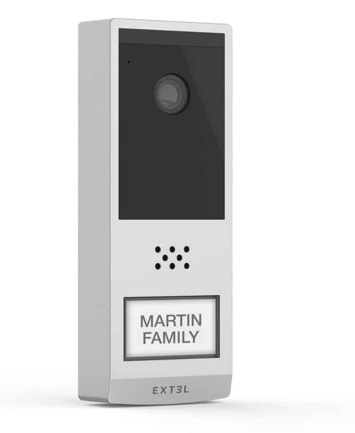
Is your intercom panel intercom no longer working or ringing? You'll need to replace your intercom panel motherboard. 
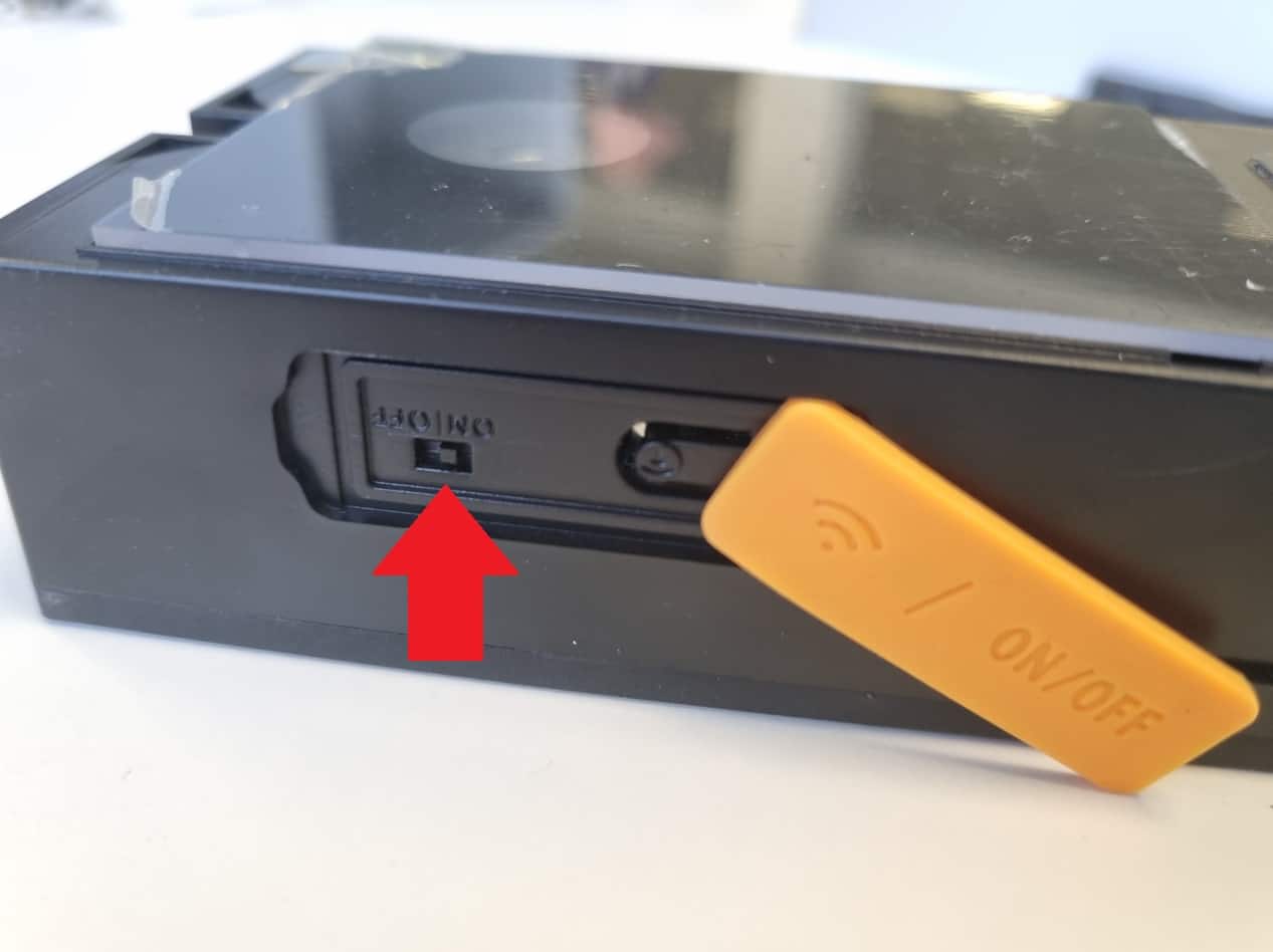
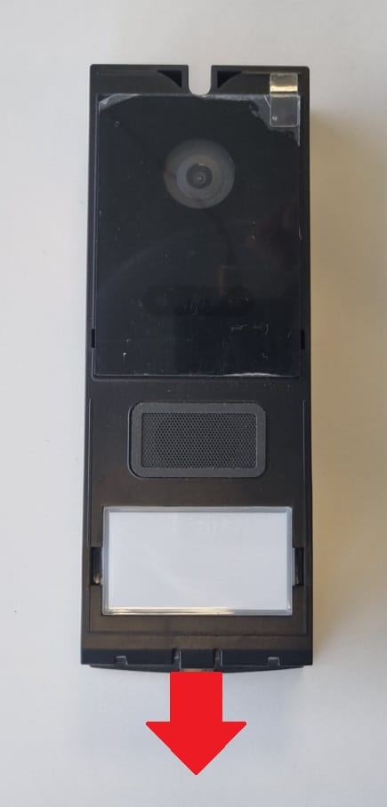
Before carrying out any work or maintenance, please switch off all components of your video door entry system and place yourself on a suitable surface to avoid scratching the lens.

This tutorial is applicable for:

Extel - 720321 - Wave 2
Difficulté : Easy
Temps nécessaire : 20 minutes
Nombre d’étapes : 5
Mise à jour : February 2025

Materials needed:

Phillips screwdriver, BTR 1.5mm, plastic spatula, precision pliers

Tutorial steps:

Step 1: Remove front panel and battery

  • Position your intercom panel to gain access to the underside.
  • Use the 1.5mm BTR screwdriver to tighten the safety screw.
  • Turn the screwdriver anti-clockwise to tighten the safety screw.
  • ATTENTION: The safety screw uses a left-hand thread.
  • Insert the 1.5mm BTR screwdriver into the left-hand slot.
  • Lever up to remove the front panel.
  • Set the ON/OFF slider to OFF.
  • Remove the battery by pulling it downwards.

Step 2: Remove the back panel

  • Turn the intercom panel over and, using a Phillips-head screwdriver, remove the 6 screws at the rear of the intercom panel.

Step 3: Dismantling the circuit board

  • Carefully disconnect the microphone connector by pulling it upwards with precision pliers. Be careful not to pull on the wires.
  • Unscrew the 4 screws holding the intercom panel to gain access to the bottom connectors.
  • Use the plastic spatula to gently lift your PCB out of its housing.
  • 1- Carefully disconnect the speaker connector
  • 2- Carefully disconnect the connector from the call button
  • 3- Carefully disconnect the infrared LED connector
  • Tilt the circuit board to the left to gain access to the antenna.

Step

  • Using the Phillips screwdriver, disconnect the antenna retaining lug.
  • You can now remove the circuit board.

Step 4: Installing the new circuit board

  • Install the new circuit board in the reverse order of disassembly.
  • Reposition the antenna and reattach it to the chassis.
  • Temporarily reposition the new circuit board on the chassis.
  • Ensure that the battery connector seal is correctly positioned
  • First, reconnect the lower connections:
  • 1- Speaker
  • 2- Call button
  • 3- Infrared LEDs


  • Make sure the antenna wire is positioned on the left side of the chassis and reinstall the circuit board.
  • To aid positioning, guide holes are provided on the circuit board.
  • Make sure the ON/OFF switch on intercom panel is easily accessible.
  • Make sure the antenna wire is always correctly positioned and not twisted or pinched.
  • Using a Phillips screwdriver, tighten the 4 screws holding the circuit board in place.
  • Reconnect the microphone.

Step 5: Reassembling the door station

  • Turn the intercom panel over and, using the Phillips screwdriver, screw back the 6 screws at the rear of the intercom panel.
  • Reconnect the battery. Pay attention to the direction of insertion.
  • Switch to ON position.


  • Don’t forget to reassociate the monitor and intercom panel.
  • Test short-range operation before final reinstallation.
Keep in touch
Youtube Linkedin

Follow us on social networks

About Avidsen
  • Who are we?
  • Contact
  • Who are we?
  • Contact
Support
  • Avidsen Technical Support
  • Extel brand technical support
  • Philips technical support
  • Thomson Technical Support
  • Avidsen Technical Support
  • Extel brand technical support
  • Philips technical support
  • Thomson Technical Support
Avidsen group brand
  • Avidsen Brand
  • Extel Brand
  • Philips Brand
  • Thomson Brand
  • Avidsen Brand
  • Extel Brand
  • Philips Brand
  • Thomson Brand
Copyright 2025 © All rights reserved Avidsen
  • Legal Notice
  • Personal data protection policy
  • Terms and Conditions of Use
  • Legal Notice
  • Personal data protection policy
  • Terms and Conditions of Use
Thank you for your rating!
Thank you for your rating and comment!
This page was translated from: French
Please rate this translation:
Your rating:
Change
Please give some examples of errors and how would you improve them: